
Concept explainers
Videos
In the circuit of Fig. 7.93,
- (a) Find R, L, and τ.
- (b) Calculate the energy dissipated in the resistance for 0 < t < 0.5 ms.
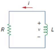
Figure 7.93
For Prob. 7.13.
(a)
Find the value of resistance R, inductance L and also find the time constant
Answer to Problem 13P
The value of resistance R in the circuit is
Explanation of Solution
Given data:
The voltage
The current
Formula used:
Write the general expression to find the voltage across the resistor using Ohms law.
Here,
Write the expression to find the time constant for RL circuit.
Here,
R is the resistance of the resistor, and
L is the inductance of the inductor.
Write the general expression to find the voltage response in the RL Circuit.
Here,
Calculation:
Substitute
Rearrange the above equation to find resistance R.
Compare the given voltage
Rearrange the equation (4) to find the time constant
Substitute
Rearrange the equation (5) to find the inductance L in Henry.
Conclusion:
Thus, the value of resistance R in the circuit is
(b)
Find the value of energy dissipated in the resistance for
Answer to Problem 13P
The value of energy dissipated in the resistance for
Explanation of Solution
Given data:
The energy dissipated in the resistance for the time limits
Formula used:
Write the expression to find the energy dissipated in the resistor.
Here,
Write the expression to find the power dissipated in the resistor.
Here,
Substitute equation (7) in equation (6) to find the energy dissipated in the resistor w.
Calculation:
Substitute
Rewrite the equation (9) as follows,
Reduce the equation (10) to find the energy dissipated in the resistor w in joules.
Converting the unit J to
Conclusion:
Thus, the value of energy dissipated in the resistance for
Want to see more full solutions like this?
Chapter 7 Solutions
FUND.OF ELECTRIC CIRCUITS>CUSTOM<


- In the circuit below, the switch is closed at t=0 s. It is known that the voltage across the capacitor at t=0.2 s is Vc( t = 0.2 ) = 10.31 V. In this case, what will be the voltage Vc( t = 0.1 ) of the capacitor at t=0.1 s? Calculate.arrow_forwardIn the circuit below, the switch is closed at t=0 s. It is known that the voltage across the capacitor at t=0.2 s is Vc( t = 0.2 ) = 10.31 V. What is the initial energy of the capacitor in this case? Calculate.arrow_forwardthe input to the series RC circuit of fig 7.27,is the square wave form of fig. 7.2, compute the voltage vc(t) across the capacitor. consider only the first 3 terms of the series, and assume omega=1.arrow_forward
- 1. 7.1 The switch in the circuit shown has been closed for a long time andis opened at t=0.1. a) Calculate the initial value of i.arrow_forwardIn response to a change introduced by a switch at t = 0, the current flowing through a 100 μF capacitor, defined in accordance with the passive sign convention, was observed to be i(t) = −0.4e−0.5t mA (for t > 0). If the final energy stored in the capacitor (at t = ∞) is 0.2 mJ, determine υ(t) for t ≥ 0.arrow_forwardA series LR circuit has a variable inductor with theinductance L(t) is defined by intervals.Find the current i(t) if the resistance is 0.2 ohms, the voltageapplied is E(t) = 4 volts; knowing that i(0) = 0.arrow_forward
- *Assume that at the instant the 2 A dc current source is applied to the circuit in (Figure 1), the initial current in the 25 mH inductor is 1 A, and the initial voltage on the capacitor is 50 V (positive at the upper terminal).* Pt A. Find the expression for iL(t) for t≥0 if R equals 12.5 Ωarrow_forward1. Determine ?(?) ??? ? > 0.2.For the circuit below, determine: ?. ? (0^-), ? the time constant of the circuit at t > 0, and (?) ?(?) ??? ? > 0.arrow_forward11. 7.11 The switch in the circuit seen has been in position 1for a long time. At t=0, the switch moves instantaneously to position 2.Find the value of R so that 20% of the initial energy stored in the 30 mHinductor is dissipated in R in 15 μs.arrow_forward
- The switch in the circuit shown in the figure below has been open for a long time. It closes at t = 0s, then 1-Calculate the initial stored energy in the capacitor 2- Find the current iR(t) for t >= 0. 3- Plot the current iR(t) for t >= 0.arrow_forwardThe current (I) flowing in a circuit containing a capacitor that is discharging changes with time (t) according to the equation:I = Io e-t/(CR)A circuit contains a capacitor of 30 x 10-6 F in series with a resistance of 4.7 x 10 5 Ω. If the initial current is 3.5A , calculate the current after 15 s.arrow_forwardFor the following circuit obtain: (a) the response v(t) for t>0, (b) the current i(t) through the inductor for t>0.arrow_forward
 Introductory Circuit Analysis (13th Edition)Electrical EngineeringISBN:9780133923605Author:Robert L. BoylestadPublisher:PEARSON
 Delmar's Standard Textbook Of ElectricityElectrical EngineeringISBN:9781337900348Author:Stephen L. HermanPublisher:Cengage Learning
 Programmable Logic ControllersElectrical EngineeringISBN:9780073373843Author:Frank D. PetruzellaPublisher:McGraw-Hill Education
 Fundamentals of Electric CircuitsElectrical EngineeringISBN:9780078028229Author:Charles K Alexander, Matthew SadikuPublisher:McGraw-Hill Education
 Electric Circuits. (11th Edition)Electrical EngineeringISBN:9780134746968Author:James W. Nilsson, Susan RiedelPublisher:PEARSON
 Engineering ElectromagneticsElectrical EngineeringISBN:9780078028151Author:Hayt, William H. (william Hart), Jr, BUCK, John A.Publisher:Mcgraw-hill Education,