
Concept explainers
Videos
In the figure is a proposed shaft design to be used for the input shaft a in Prob. 7–17. A ball bearing is planned for the left bearing, and a cylindrical roller bearing for the right.
(a) Determine the minimum fatigue factor of safety by evaluating at any critical locations. Use the DE-ASME Elliptic fatigue criterion.
(b) Check the design for adequacy with respect to deformation, according to the recommendations in Table 7–2.
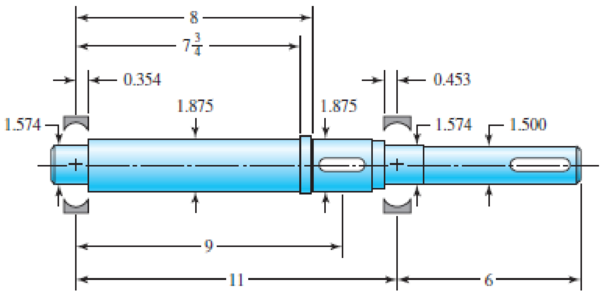
Problem 7–18
Shoulder fillets at bearing seat 0.030-in radius, others
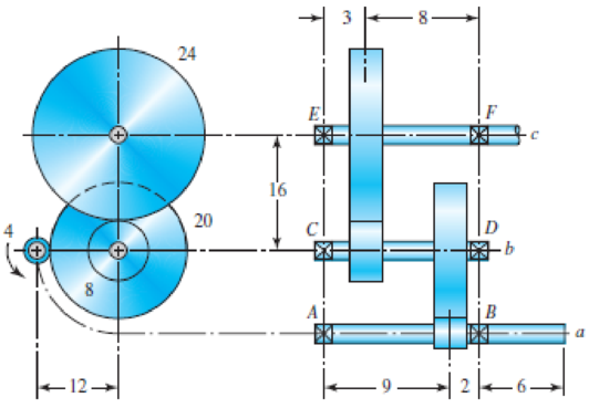
In the double-reduction gear train shown, shaft a is driven by a motor attached by a flexible coupling attached to the overhang. The motor provides a torque of 2500 lbf · in at a speed of 1200 rpm. The gears have 20° pressure angles, with diameters shown in the figure. Use an AISI 1020 cold-drawn steel. Design one of the shafts (as specified by the instructor) with a design factor of 1.5 by performing the following tasks.
(a) Sketch a general shaft layout, including means to locate the gears and bearings, and to transmit the torque.
(b) Perform a force analysis to find the bearing reaction forces, and generate shear and bending moment diagrams.
(c) Determine potential critical locations for stress design.
(d) Determine critical diameters of the shaft based on fatigue and static stresses at the critical locations.
(e) Make any other dimensional decisions necessary to specify all diameters and axial dimensions. Sketch the shaft to scale, showing all proposed dimensions.
(f) Check the deflection at the gear, and the slopes at the gear and the bearings for satisfaction of the recommended limits in Table 7–2.
(g) If any of the deflections exceed the recommended limits, make appropriate changes to bring them all within the limits.
Problem 7–17
Dimensions in inches.
Want to see the full answer?
Check out a sample textbook solution
Chapter 7 Solutions
Shigley's Mechanical Engineering Design (McGraw-Hill Series in Mechanical Engineering)


- A rotating shaft of 40×4 mm AISI 1018 cold-drawn steel tubing has a 6 mm diameter hole drilled transversely through it. Estimate the factor of safety guarding against fatigue and static failures using the Gerber and Langer failure criteria for the following loading conditions: a. The shaft is subjected to a completely reversed torque of 120 N.m in phase with a completely reversed bending moment of 150 N.m. b. The shaft is subjected to a pulsating torque fluctuating from 20 to 160 N.m and as steady bending moment of 150 N.m.arrow_forwardThe figure shows a shaft mounted in bearings at A and D and having pulleys at B and C. The forces shown acting on the pulley surfaces represent the belt tensions. The shaft is to be made of AISI 1035 CD steel. The shaft is rotating at speed of 1000 rpm. Find the minimum factor of safety for fatigue based on infinite life. If the life is not infinite, estimate the number of cycles. Be sure to check for yielding. Take shaft diameter to be 1.5 inches.arrow_forwardA helical cast steel gear with 30o helix angle has to transmit 35 kW at 2000 rpm. If the gears has 25 teeth, find the necessary module, pitch diameters and face width for 20o full depth involute teeth. The static stress for cast steel may be taken as 100 MPa. The face width may be taken as 3 times to normal pitch. The tooth form factor is given by the expression y'= 0.154-0.912/TE, where TE represents the equivalent number of teeth. the velocity factor is given by Cv=6/(6+v), where v is the peripheral speed of the gear in m/s.arrow_forward
- The shaft in the figure is mounted with a gear wheel key. Shaft material 42CrMo4 The weight of the gear on the shaft is 0.9 kg, dimension, surface and notch factors KbK / Kç = 0.83, shaft speed n = 1120 rpm, shaft transmitted power 7.5 kW, force on shaft Fn = F = 2680 N Since the desired safety coefficient is Ssafe = 2; Check the safety of the shaftarrow_forward5. Design a sleeve coupling for the transmission of 12 kW at 300 rpm by two connected steel shafts. Take service factor KS 1.25. The sleeve is made of CI. The key and the shaft are made of the same material. Allowable stress: Shear stresses in key and shaft 50 MPa Crushing stress in key= 100 MPa Shear stress in CI sleeve = 10 MPaarrow_forwardThe solid steel rotating shaft in the figure is supported at B and C, and is driven by a gear, not seen, which is linked to spur gear D which has a pitch diameter of 150 mm. The drive gear force F acts at a pressure angle of 20 degrees. The shaft transmits a torque to point A of Ta-350 N.m. The properties of machined steel shaft are Sy-420 MPa and Sut-560MPa. Use a safety factor of 2.5 and determine the minimum allowable diameter in section B and C. Assume sharp felt radii at the bearing shoulders to estimate the stress concentration factors.Explain.arrow_forward
- The motor shown in the figure supplies 16.5 kW at 1540 rpm at A. Shafts (1) and (2) are each solid 28 mm diameter shafts. Shaft (1) is made of an aluminum alloy [ G=26 GPa], and shaft (2) is made of bronze [ G=45 GPa]. The shaft lengths are L1=3.3m and L2=2.9m, respectively. Gear B has 56 teeth, and gear C has 97 teeth. The bearings shown permit free rotation of the shafts. Determine: the rotation angle of gear D with respect to flange A. [Answer φD/A = 0.314 rad]arrow_forwardA single stage spur gear gearbox has a module of 1.5mm and an input speed of 1500.p.m. and a pinion with 15 teeth. The overall ratio of the gearbox is 6:1 and the gearbox is transmitting a power of 6000W. If the factor of safetv is to be reduced to an absolute minimum acceptable value and the gears are to be made from a material with a Yield stress of 540 MPa, what is the face width of the gears (in mm) Express your answer in the form 21.00 ie with two decimal place an no unitsarrow_forwardA motor is to transmit 150 kW to a piece of mechanical equipment. The power is transmitted through a solid structural steel shaft. Failure is by yielding, and the factor of safety is 1.25. The designer has the freedom to operate the motor at 60 rpm or 6000 rpm. For each case, determine the minimum shaft diameter. Shafts are available with diameters in increments of 5 mm. If weight is important, which speed would be used?arrow_forward
- Find the diameter of a shaft made of 37 Mn 2 steel having the ultimate tensile strength as 600 MPa and yield stress as 440 MPa. The shaft is subjected to completely reversed axial load of 200 kN. Neglect stress concentration factor and assume surface finish factor as 0.8. The factor of safety may be taken as 1.5. [arrow_forwardTorque in = 40nm Holding torque out = 896nm 8.Using your answers from the gear box above, and given that the input shaft has a diameter of 12 mm and the output shaft has a diameter of 15 mm, both shafts are made from aluminium. When this transmission system was operated, it failed. Identify the position where the failure occurred and the reason for this failure. Suggests improvements to the system to overcome the failure mode. The shear strength of aluminium is 207 MPa.arrow_forwardA motor driving a solid circular steel shaft with diameter d = 1.5 in, transmits 50 hp to a gear at B, The allowable shear stress in the steel is 6000 psi. Calculate the required speed of rotation (number of revolutions per minute) so that the shear stress in the shaft does not exceed the allowable limit.arrow_forward
 Mechanics of Materials (MindTap Course List)Mechanical EngineeringISBN:9781337093347Author:Barry J. Goodno, James M. GerePublisher:Cengage Learning