
Videos
Determine the normal force, shear force, and moment at point C.
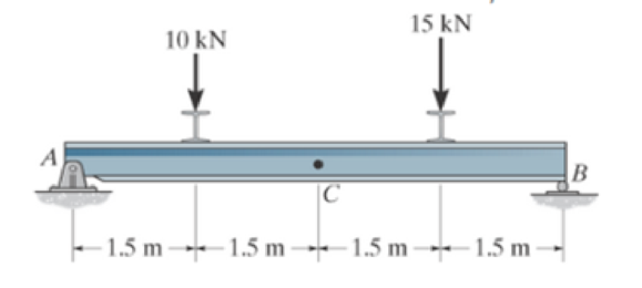
Prob. F7-1
The normal force, shear force, and moment at point C.
Answer to Problem 1FP
The normal force at point C,
The shear force at point C,
The moment at point C,
Explanation of Solution
Assumption:
- Consider the state of the member as tension, where the force is pulling the member, and as compression, where the force is pushing the member.
- The normal force is positive if it creates tension; a positive shear force acting on the segment causes it to rotate clockwise, and a positive bending moment acting on the segment will cause it to bend and concave upwards. Loadings that are opposite to these are considered negative.
- Consider the force indicating the right side as positive and the left side as negative, in the horizontal components of forces.
- Consider the force indicating upside as positive and downside as negative, in the vertical components of forces.
- Consider the clockwise movement as negative and the anti-clockwise movement as positive, wherever applicable.
- The method of sections can be used to determine the internal loadings.
Determine the reactions:
Entire beam:
Show the free body diagram of the entire beam as in Figure (1).
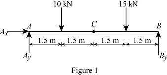
Using Figure (1),
Moment at point A:
Determine the vertical reaction at point B by taking the moment about point A.
Solve Equation (I).
Determine the forces and moment:
Segment CB:
Show the free body diagram of the segment CB as in Figure (2).
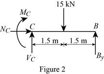
Using Figure (2),
Along the vertical direction:
Determine the shear force at point C by resolving the vertical component of forces.
Along the horizontal direction:
Determine the normal force at point C by resolving the horizontal component of forces.
Moment about point C:
Determine the moment at point C by taking the moment about point C.
Conclusion:
Substitute 13.75 kN for
Thus, the shear force at point C,
Refer to Equation (III).
Thus, the normal force at point C,
Substitute 13.75 kN for
Thus, the moment at point C,
Want to see more full solutions like this?
Chapter 7 Solutions
EBK ENGINEERING MECHANICS


- F7-2. Determine the internal normal force, shear force, and bending moment at point Cin the beam. 200 N/m 100 N/m 15m 1.5 m-arrow_forward7-11. The shaft is supported by a journal bearing at A and a thrust bearing at B. Determine the normal force, shear force, and moment at a section passing through (a) point C, which is just to the right of the bearing at A, and (b) point D, which is just to the left of the 3000-lb force. 3000 lb 2500 lb 75 lb/ft B 6 ft- -12 ft- 2 ftarrow_forwardDetermine the internal normal force, shear force, and moment at point E.arrow_forward
- Determine the normal forces, shear force, and moment at points Dand Efor the 2-member frame. 1.5 m C -2 m |D E 4 m 250 N/m B 300 N/marrow_forward*7-60. The shaft is supported by a smooth thrust bearing at A and a smooth journal bearing at B. Draw the shear and moment diagrams for the shaft. 6 ft 300 lb/ft Prob. 7-60 6 ftarrow_forward7-27. Determine the internal normal force, shear force, and moment at point C. B E 200 N 1 m D 800 N· m m -2 m-arrow_forward
- 1. Determine the normal force, shear force, and moment at point C. 10 kN C -1.5 m 1.5 m 1.5 m 15 kN -1.5 m Barrow_forward4143. Replace this loading by an equivalent resultant force and specily its location, measured from point O. 6KNim 4 kN/m I!! 2m -15m- Prob. 4-143arrow_forwardFI-6. Determine the resultant internal normal force, shear force, and bending moment at point Cin the beam. 5 KN /marrow_forward
- 6-3. The engine crane is used to support the engine, which has a weight of 1200 lb. Draw the shear and moment diagrams of the boom ABC when it is in the horizontal position shown. 4 ft 3 ft B -5 ft Prob. 6-3arrow_forwardDetermine the internal normal force, shear force, and the moment at points C and D.arrow_forwardDetermine the normal force, shear force, and moment at points F and E. 50 lb/ft - 3 ft E 2 ft B 6 ft C 4 ft F D 2 ftarrow_forward
 Elements Of ElectromagneticsMechanical EngineeringISBN:9780190698614Author:Sadiku, Matthew N. O.Publisher:Oxford University Press
 Mechanics of Materials (10th Edition)Mechanical EngineeringISBN:9780134319650Author:Russell C. HibbelerPublisher:PEARSON
 Thermodynamics: An Engineering ApproachMechanical EngineeringISBN:9781259822674Author:Yunus A. Cengel Dr., Michael A. BolesPublisher:McGraw-Hill Education
 Control Systems EngineeringMechanical EngineeringISBN:9781118170519Author:Norman S. NisePublisher:WILEY
 Mechanics of Materials (MindTap Course List)Mechanical EngineeringISBN:9781337093347Author:Barry J. Goodno, James M. GerePublisher:Cengage Learning
 Engineering Mechanics: StaticsMechanical EngineeringISBN:9781118807330Author:James L. Meriam, L. G. Kraige, J. N. BoltonPublisher:WILEY