
Concept explainers
Calculate the horizontal deflection and vertical deflection at joint B.
Answer to Problem 2P
The horizontal deflection at joint B is
The vertical deflection at joint B is
Explanation of Solution
Given information:
The truss is given in the Figure.
The value of E is 70 GPa and the value of A is
Procedure to find the deflection of truss by virtual work method is shown below.
- For Real system: If the deflection of truss is determined by the external loads, then apply method of joints or method of sections to find the real axial forces (F) in all the members of the truss.
- For virtual system: Remove all given real loads, apply a unit load at the joint where is deflection is required and also in the direction of desired deflection. Use method of joints or method of sections to find the virtual axial forces
- Finally use the desired deflection equation.
Apply the sign conventions for calculating reactions, forces and moments using the three equations of equilibrium as shown below.
- For summation of forces along x-direction is equal to zero
- For summation of forces along y-direction is equal to zero
- For summation of moment about a point is equal to zero
Method of joints:
The negative value of force in any member indicates compression (C) and the positive value of force in any member indicates tension (T).
Condition for zero force members:
- 1. If only two non-collinear members are connected to a joint that has no external loads or reactions applied to it, then the force in both the members is zero.
- 2. If three members, two of which are collinear are connected to a joint that has no external loads or reactions applied to it, then the force in non-collinear member is zero.
Calculation:
Consider the real system.
Find the member axial force (F) for the real system using method of joints:
Let
Let
Sketch the free body diagram of the truss as shown in Figure 1.
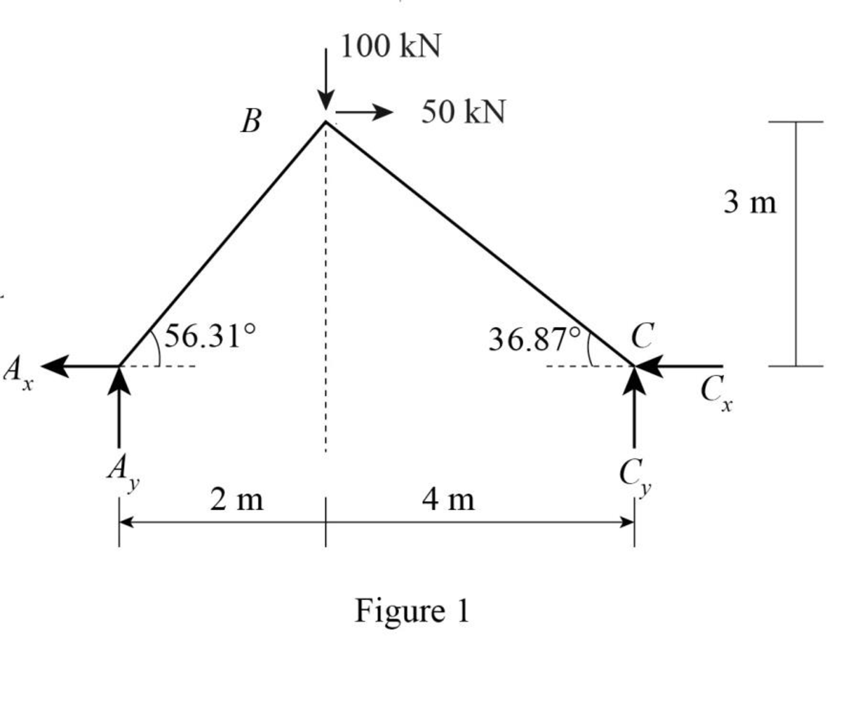
Refer to Figure 1.
Find the angle made by the member AB with respect to the horizontal axis.
Find the angle made by the member BC with respect to the horizontal axis.
Sketch the free body diagram of joint B as shown in Figure 2.
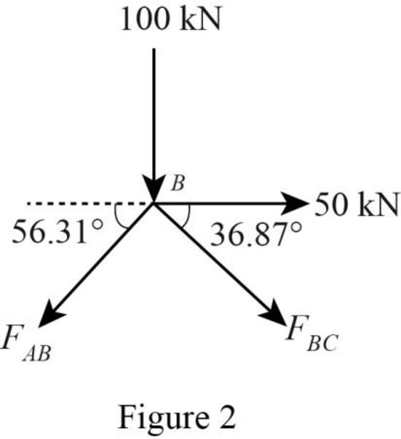
Apply equilibrium equation to the free body diagram of joint B:
Summation of forces along y-direction is equal to 0.
Summation of forces along x-direction is equal to 0.
Solve Equation (1) and Equation (2).
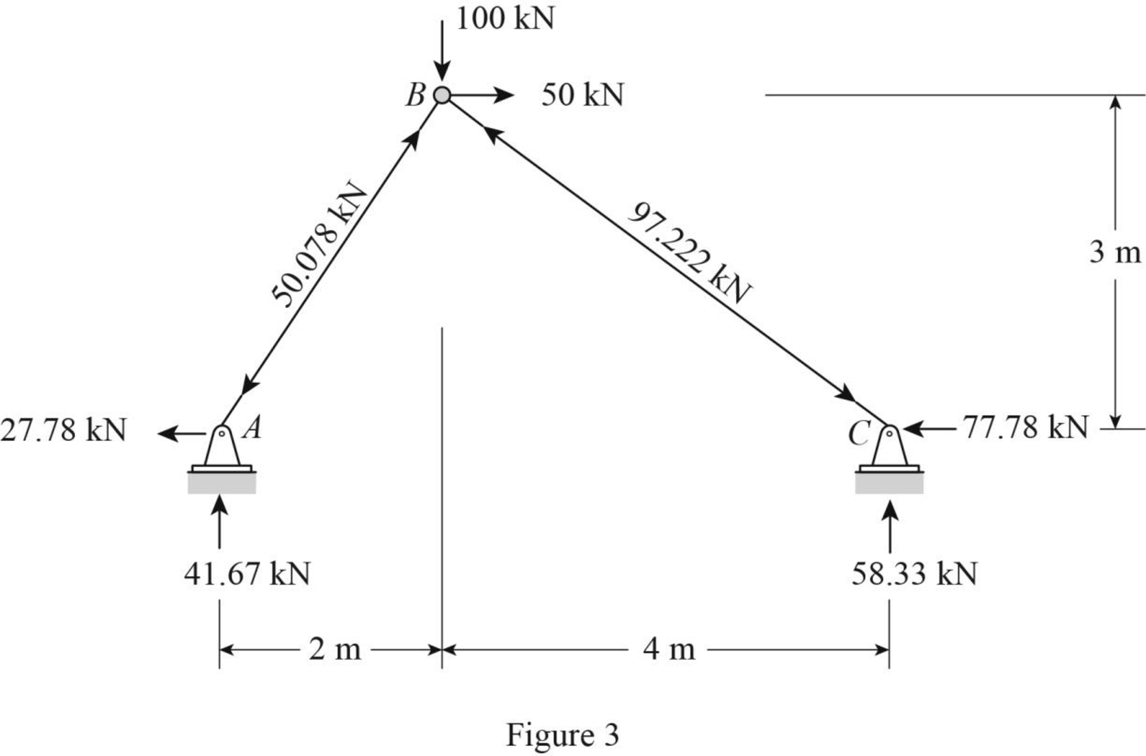
Sketch the resultant diagram of the real forces as shown in Figure 3.
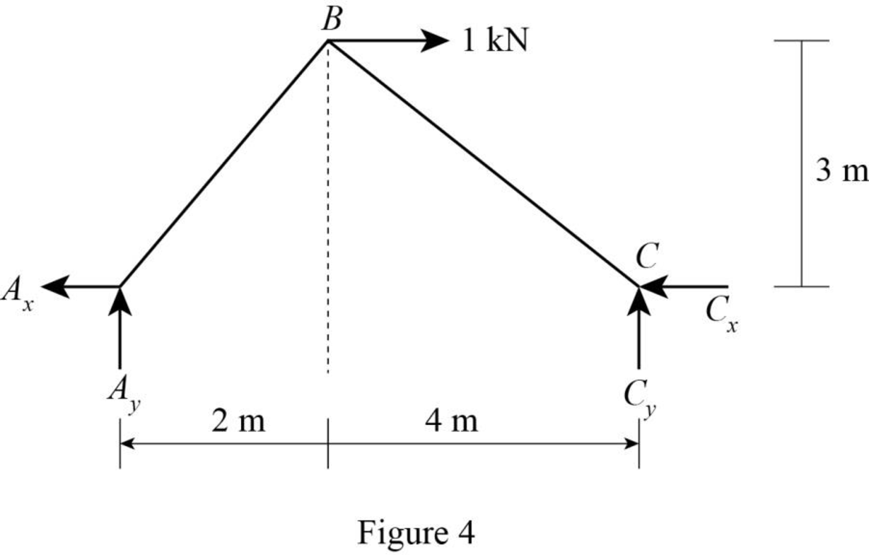
Consider the virtual system:
For horizontal deflection apply l k at joint B in horizontal direction.
Find the member axial force (
Sketch the free body diagram of the truss due to virtual load as shown in Figure 4.
Find the reactions at the supports using equilibrium equations:
Summation of moments about C is equal to 0.
Summation of forces along y-direction is equal to 0.
Consider AB,
Summation of moments about B is equal to 0.
Summation of forces along x-direction is equal to 0.
Sketch the free body diagram of joint B as shown in Figure 5.
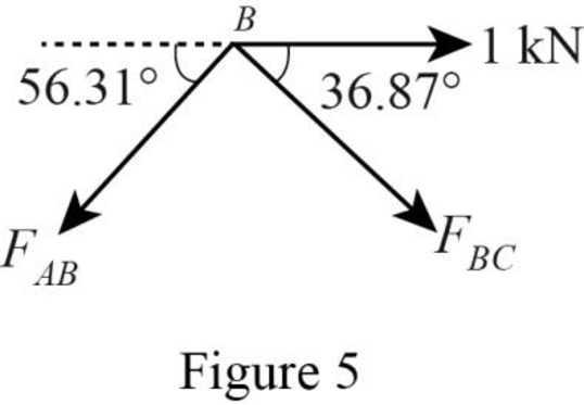
Apply equilibrium equation to the free body diagram of joint B:
Summation of forces along y-direction is equal to 0.
Summation of forces along x-direction is equal to 0.
Solve Equation (3) and Equation (4).
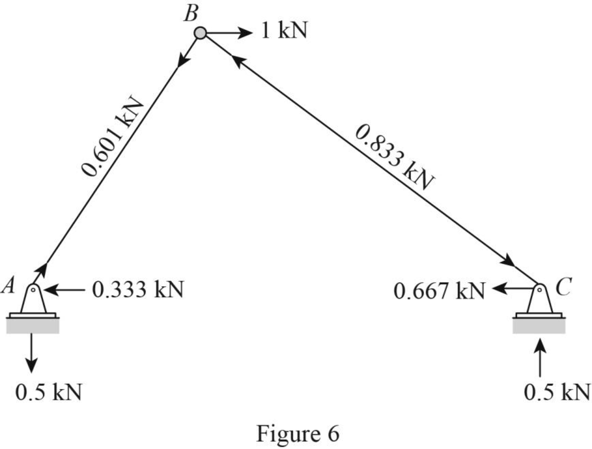
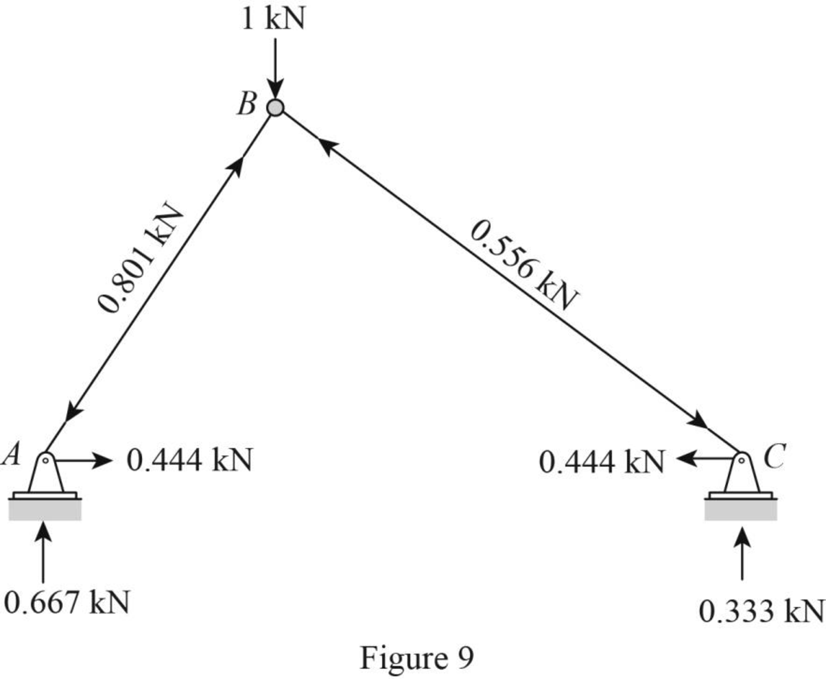
Sketch the resultant diagram of the virtual system
Consider the virtual system:
For vertical deflection apply l k at joint B in vertical direction.
Find the member axial force
Sketch the free body diagram of the truss as shown in Figure 7.
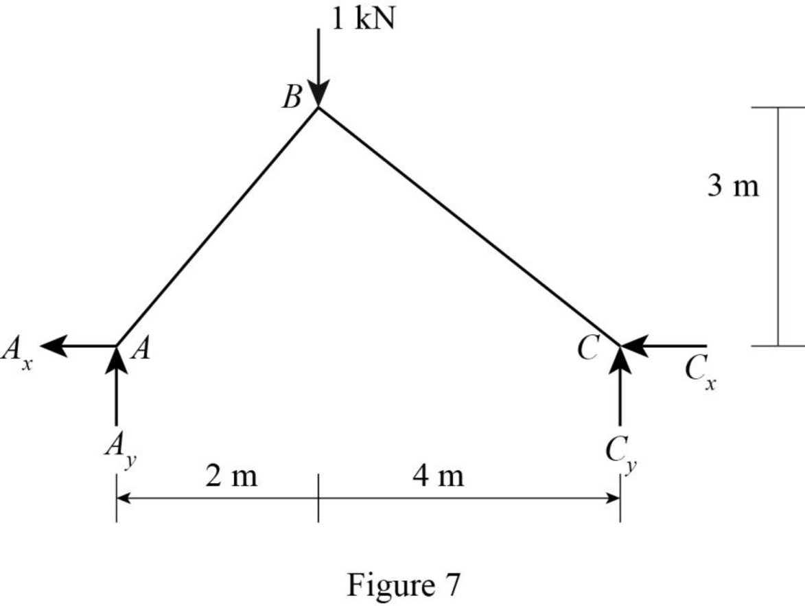
Find the reactions at the supports using equilibrium equations:
Summation of moments about C is equal to 0.
Summation of forces along y-direction is equal to 0.
Consider AB,
Summation of moments about B is equal to 0.
Summation of forces along x-direction is equal to 0.
Sketch the free body diagram of joint B as shown in Figure 8.
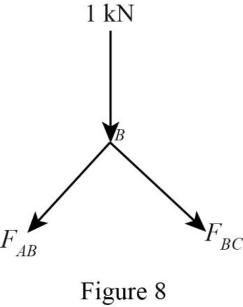
Apply equilibrium equation to the free body diagram of joint B:
Summation of forces along y-direction is equal to 0.
Summation of forces along x-direction is equal to 0.
Solve Equation (5) and Equation (6).
Sketch the resultant diagram of the virtual system
The expression to find the deflection
Here, L is the length of the member, A is the area of the member, and E is the young’s modulus of the member.
For E and A is constant, the expression becomes,
Find the length of member AB using given Figure.
Find the product of
| Member |
L | |||||
| AB | 3.606 | |||||
| BC | 5 | |||||
Find the horizontal deflection at joint B
Substitute
Therefore, the horizontal deflection at joint B is
Find the vertical deflection at joint B
Substitute
Therefore, the vertical deflection at joint B is
Want to see more full solutions like this?
Chapter 7 Solutions
Structural Analysis

