Understanding Motor Controls
3rd Edition
ISBN: 9781305498129
Author: Stephen L. Herman
Publisher: Cengage Learning
expand_more
expand_more
format_list_bulleted
Concept explainers
Videos
Textbook Question
Chapter 7, Problem 4RQ
Refer to the schematic in Figure 7-10. Assume that when the START button is pressed, the control transformer fuse blows. What is the most likely cause of this trouble?
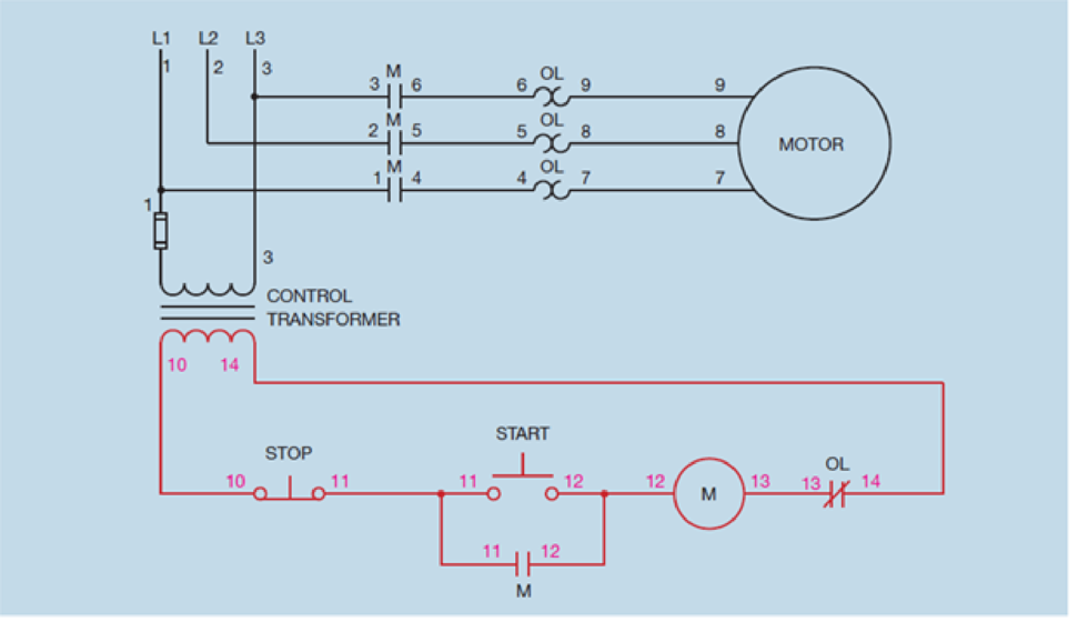
Figure 7-10 Numbers are placed beside all components.
Expert Solution & Answer

Trending nowThis is a popular solution!

Chapter 7 Solutions
Understanding Motor Controls
Ch. 7 - Refer to the circuit shown in Figure 7-10. If wire...Ch. 7 - Assume that when the START button is pressed M...Ch. 7 - Explain the difference between a motor starter and...Ch. 7 - Refer to the schematic in Figure 7-10. Assume that...Ch. 7 - Explain the difference between load and auxiliary...Ch. 7 - Prob. 6RQCh. 7 - In a schematic diagram, what does a dashed line...
Knowledge Booster


Learn more about
Need a deep-dive on the concept behind this application? Look no further. Learn more about this topic, mechanical-engineering and related others by exploring similar questions and additional content below.Similar questions
- Refer to the transformer shown in Figure 5-13 to answer the following questions. The transformer shown in Figure 5-13 is supplying 325 volt amperes to a load. The primary voltage is 240 volts. What is the primary current? Figure 5-13 Autotransformer practice problems.arrow_forwardRefer to the circuit shown in Figure 2614. When the START button is pressed, the control transformer fuse blows immediately. Which of the following could not cause this problem? a. Control relay coil CR is shorted. b. Starter coil 1M is shorted. c. Contactor coil S is shorted. d. Contactor coil 2M is shorted.arrow_forwardRefer to the circuit shown in Figure 5-29. Is the thermostat contact normally open, normally closed, normally closed held open, or normally open held closed? Figure 5-29 The contactor contains both load and auxiliary contacts.arrow_forward
- Refer to the circuit shown in Figure 7-10. If wire number 11 were disconnected at the normally open auxiliary M contact, how would the circuit operate? Figure 7-10 Numbers are placed beside all components.arrow_forwardRefer to the transformer shown in Figure 5-13 to answer the following questions. What is the turns ratio of the winding between points B and E as compared to the winding between points D and E? Figure 5-13 Autotransformer practice problems.arrow_forwardRefer to the circuit shown in Figure 107. Assume that when the start button is pressed the motor does not start, but when the inch push button is pressed the motor runs at reduced speed. Which of the following could NOT cause this problem? a. The control transformer fuse is blown. b. M starter coil is defective. c. The start push button is defective. d. The stop push button is defective.arrow_forward
- Name three factors that determine the amount of induced voltage.arrow_forwardRefer to the circuit shown in Figure 97. Assume that when the forward push button is pressed the motor does not start, but when the reverse push button is pressed the motor will start in the reverse direction. When the stop button is pressed the motor stops running. Which of the following could NOT cause this problem? a. The forward push button is defective. b. The F starter coil is open. c. The overload auxiliary contact is open. d. The normally closed R contact is open.arrow_forwardRefer to Figure 21–1 to answer the following questions. When switch HOA SW 122 is in the off position, which contacts have connection between them?arrow_forward
- Refer to the circuit shown in Figure 4221. Assume that the THIRD SPEED push button is pressed. The motor starts in second speed, skipping first speed. After 5 seconds, the motor accelerates to third speed. Which of the following could cause this problem? a. S1 contactor coil is open. b. CR1 contactor coil is open. c. TRl timer coil is open. d. S1 load contacts are shorted.arrow_forwardRefer to the circuit shown in Figure 33–7. When the low speed push button is pressed, the motor begins to run in low speed. When the high speed push button is pressed, the motor stops running. Which of the following could cause this problem? The 1L contactor coil is open. H contactor coil is open. PR relay coil is open. The 2L contactor coil is open.arrow_forwardRefer to the schematic diagram in Figure 318. Assume that the motor is not running. When the third speed push button is pressed, the motor starts in its lowest speed. After a delay of 3 seconds, the motor accelerates to second speed and 3 seconds later to third speed. After a period of about 1 minute, the fourth speed push button is pressed, but the motor does not accelerate to fourth speed. Which of the following could cause this problem? a. Control relay CR2 coil is open. b. S2 contactor coil is open. c. CR3 coil is shorted. d. S3 contactor coil is open.arrow_forward
arrow_back_ios
SEE MORE QUESTIONS
arrow_forward_ios
Recommended textbooks for you
 Understanding Motor ControlsMechanical EngineeringISBN:9781337798686Author:Stephen L. HermanPublisher:Delmar Cengage Learning
 Electrical Transformers and Rotating MachinesMechanical EngineeringISBN:9781305494817Author:Stephen L. HermanPublisher:Cengage Learning
Understanding Motor Controls
Mechanical Engineering
ISBN:9781337798686
Author:Stephen L. Herman
Publisher:Delmar Cengage Learning
Electrical Transformers and Rotating Machines
Mechanical Engineering
ISBN:9781305494817
Author:Stephen L. Herman
Publisher:Cengage Learning
Hydronics Step by Step; Author: Taco Comfort Solutions;https://www.youtube.com/watch?v=-XGNl9kppR8;License: Standard Youtube License