
Videos
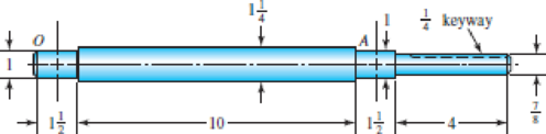
The figure shows a proposed design for the industrial roll shaft of Prob. 7–4. Hydrodynamic film bearings are to be used. All surfaces are machined except the journals, which are ground and polished. The material is 1035 HR steel. Perform a design assessment. Is the design satisfactory?
Problem 7–6
Bearing shoulder fillets 0.030 in, others
Weather the design is satisfactory or not.
Answer to Problem 6P
The design is satisfactory for crown gear.
Explanation of Solution
Write the expression for force acting on roller.
Here, normal force is
Write the expression for force acting on C along z axis.
Here, force on C in z axis is
Write the expression for torque.
Here, torque is
Write the expression for force at B along z axis.
Here, force at B along z axis is
Write the expression for force at B along y-axis
Here, force at B along y-axis is
Write the expression for moment about O.
Write the expression for moment about A.
Write the expression for moment at point C.
Write the expression for moment at A.
Write the expression for moment about O.
Write the expression for moment about A.
Write the expression for moment at point C along z-axis.
Write the expression for moment at A along z-axis.
Write the expression for total moment.
Here, bending moment in x-y plane is
Write the expression for total moment at D.
Here, moment on x-y plane at D is
Write the moment equation in x-y plane.
Integrate Equation (XVI).
Integrate Equation (XVII).
Apply boundary Equation, substitute
Substitute
Substitute
Substitute
Write the moment equation in x-z plane.
Integrate Equation (XVIII).
Integrate Equation (XIX).
Substitute
Substitute
Substitute
Substitute
Write the expression for flexural rigidity.
Here, flexural rigidity is
Write the expression for deflection at A.
Here, speed is
Write the expression for relative deflection.
Here, force is
Write the expression for deflection at B.
Write the expression for deflection at z.
Here, deflection at A is
Write the expression for relative deflection.
Here, force is
Write the expression for deflection at B.
Here, deflection at B is
Write the expression for gear mesh.
Here, gear mesh at B is
Write the expression for concentration factor for bending.
Here, concentration factor for bending is
Write the expression for concentration factor torsion.
Here, concentration factor for torsion is
Write the expression for endurance limit.
Here, endurance limit is
Write the expression for surface factor.
Here, surface factor is
Write the expression for size factor.
Here, size factor is
Write the expression for endurance limit at critical path.
Here, surface modification factor is
Conclusion:
The following figure shows roller forces.
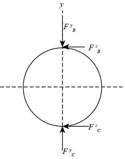
Figure-(1)
Substitute
Substitute
Substitute
Substitute
Substitute
The figure below shows the free body diagram and bending moment diagram.
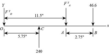
Figure-(2)
Substitute
Substitute
Substitute
The figure below shows the bending moment diagram for x-y plane.
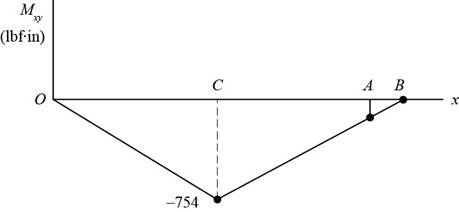
Figure-(3)
Substitute
The figure below shows free body diagram and the bending moment diagram in x-z plane.
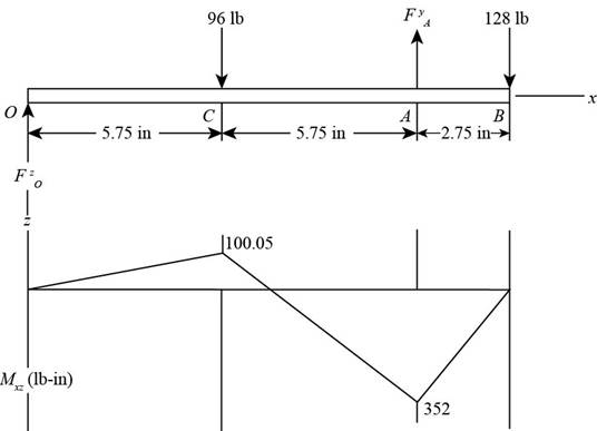
Figure-(4)
Substitute
Substitute
Substitute
Substitute
Substitute
Substitute
The figure below shows the bending moment diagram.
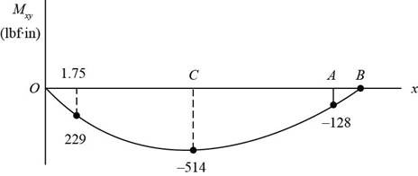
Figure-(5)
The figure below shows the forces in x-z plane.
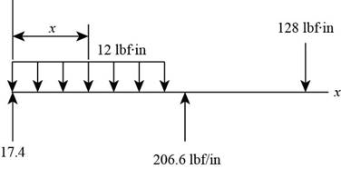
Figure-(6)
Substitute
The figure below shows the bending moment diagram.
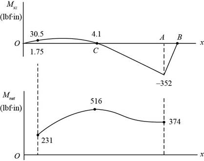
Figure-(7)
Substitute
Substitute
Calculate factor of safety.
The figure below shows forces in x-y plane.
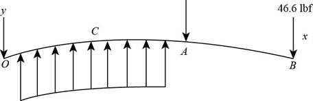
Figure-(8)
Substitute
Substitute
The figure below shows the forces on the system.
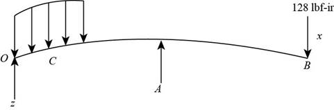
Figure-(9)
Substitute
Substitute
Substitute
Refer to table A-20, “Deterministic ASTM minimum tensile and yield strength for some hot rolled and cold drawn steels” to obtain tensile strength as
Substitute
Substitute
Substitute
Refer to table 7-1, “First iteration estimated for stress concentration factors” to obtain concentration factor for bending stress as
Refer to figure6-20, to obtain notch sensitivity as
Substitute
Substitute
Substitute
Refer to table 6-2, “Parameters for main surface condition factor” to obtain
Substitute
Substitute
Substitute
Substitute
The factor of safety is acceptable for crowned gear.
Thus, crowned gear is more reliable.
Want to see more full solutions like this?
Chapter 7 Solutions
Connect 1-semester Access Card For Shigley's Mechanical Engineering Design


- The worm shaft shown in the figure transmits 1-kW at 500 rev/min. A static forceanalysis results are also shown in the figure. Bearing A is to be an angular-contact ballbearing mounted to take the 2.75 kN thrust load. The bearing at B is to take only theradial load, so a straight roller bearing will be employed. Use an application factor of1.2, a desired life of 25 kh, and a combined reliability goal of 0.99. (a)Specify each bearing by giving all required charecteristics. (b) Determine the radial and thrust components of loads on each bearing. (c) Make a design assessment for each bearing and of the system.arrow_forwardA single deep grove ball bearing series 3, the outer ring rotates at 1500 rpm with little shock load. Bearing has a bore diameter of 45 mm, working with a load 1890 lb radial and 1250 lb axial load. Determine the rated life and median life of the bearing. Use the design factors according to the attached table.arrow_forwardTwo designs for a shaft are being considered. Both have an outside diameter of 50 mm and are 600 mm long. Oneis solid but the other is hollow with an inside diameter of 40 mm. Both are made from steel. Compare the torsionalshear stress, the angle of twist, and the mass of the two designs if they are subjected to a torque of 850 N ·m.arrow_forward
- A cylinder with a nominal 2.5 in ID, a 4.0 in OD, and a 3.0 in length is to be mated with a solid shaft with a nominal 2.5 in diameter. A medium drive fit is desired (as defined in Table 7-9). The cylinder and shaft are made from steel, with Sy = 100 kpsi and E = 30 Mpsi. The coefficient of friction for the steel interface is 0.7. a. Specify the maximum and minimum allowable diameters for both the cylinder hole and the shaft. b. Determine the torque that can be transmitted through this joint, assuming the shaft and cylinder are both manufactured within their tolerances such that the minimum interference is achieved. c. Suppose the shaft and cylinder are both manufactured within their tolerances such that the maximum interference is achieved. Check for yielding of the cylinder at its inner radius by finding the following: i. The pressure at the interface ii. The tangential and radial stresses in the cylinder, at its inner radius. iii. The factor of safety for static yielding of the…arrow_forwardThe following data apply to the machinist clamp shown in the figure: Outside diameter of screw=1/2 in.; Root diameter=0.4350 in.; Pitch (single thread)=0.05 in.; Collar friction radius=0.20 in.; Collar friction coefficient=0.15; and screw friction coefficient=0.15. Assume that the machinist can comfortably exert a maximum force of 30 lbs. on the handle.Determine: (a) the clamping force developed between the jaws of the clamp; (b) the efficiency of the clamp; (c) the torque in the screw body at section A-Aarrow_forwardA shaft is designed to transmit power of 100 kW at 180 rpm. The allowable shear stress is 50MPa and modulus of rigidity of 80 GPa. The angle of twist is not to exceed to 1° in 4-meter length A. Calculate the diameter of the shaft in inches. B.If the shaft in A is to be fitted to a hub with material SAE 0105 and fit classification of FN3, what will be the maximum and minimum stresses based on the interference of metal.arrow_forward
- 5. Design a sleeve coupling for the transmission of 12 kW at 300 rpm by two connected steel shafts. Take service factor KS 1.25. The sleeve is made of CI. The key and the shaft are made of the same material. Allowable stress: Shear stresses in key and shaft 50 MPa Crushing stress in key= 100 MPa Shear stress in CI sleeve = 10 MPaarrow_forwardThe figure shows a shaft mounted in bearings at A and D and having pulleys at B and C. The forces shown acting on the pulley surfaces represent the belt tensions. The shaft is to be made of AISI 1035 CD steel. Using distortion-energy theory with a design factor of 2, determine the minimum shaft diameter to avoid yielding.arrow_forwardA short stub shaft, made of SAE 1035, as rolled, receivers 30 hp at 300 rpm via a 12-in. spur gear, the power being delivered to another shaft through a flexible coupling. The gear is keyed (profile keyway) midway between the bearings. The pressure angle of the gear teeth 20o, N = 1.5 based on the octahedral shear stress theory with varying stresses. (a) Neglecting the radial component R of the tooth load W , determine the shaft diameter. (b) Considering both the tangential and the radial components, compute the shaft diameters. (c) Is the difference in the results of the parts (a) and (b) enough to change your choice of the shaft size?arrow_forward
- On the axis of the figure, the forces of the bearing reactions R1 are exerted. And R2; the shaft rotates at 1150 rpm and supports a bending force of 10 Kip. Use a 1095 HR steel. Specify a diameter d with a design factor of 1.6, for a 5 hour life, surfaces are machinedarrow_forwardTwo designs for shaft are being considered. Both have an outside diameter of 60 mm and are 500 mm long. One is solid but the other is hallow with an inside diameter of 40 mm, both are made from steel ( G=80 GPa). Compare the torsional shear stress, and the mass of the two designs if they are subjected to a torque of 71 N.m.arrow_forward3.A chain drive using bush roller chain transmits 5.6 kW of power. The driving shaft on an electric motor runs at 1440 r.p.m. and velocity ratio is 5. The centre distance of the drive is restricted to 550 ± 2% mm and allowable pressure on the pivot joint is not to exceed 10 N/mm2. The drive is required to operate continuously with periodic lubrication and driven machine is such that load can be regarded as fairly constant with jerk and impact. Design the chain drive by calculating leading dimensions, number of teeth on the sprocket and specify the breaking strength of the chain. Assume a factor ofarrow_forward
 Elements Of ElectromagneticsMechanical EngineeringISBN:9780190698614Author:Sadiku, Matthew N. O.Publisher:Oxford University Press
 Mechanics of Materials (10th Edition)Mechanical EngineeringISBN:9780134319650Author:Russell C. HibbelerPublisher:PEARSON
 Thermodynamics: An Engineering ApproachMechanical EngineeringISBN:9781259822674Author:Yunus A. Cengel Dr., Michael A. BolesPublisher:McGraw-Hill Education
 Control Systems EngineeringMechanical EngineeringISBN:9781118170519Author:Norman S. NisePublisher:WILEY
 Mechanics of Materials (MindTap Course List)Mechanical EngineeringISBN:9781337093347Author:Barry J. Goodno, James M. GerePublisher:Cengage Learning
 Engineering Mechanics: StaticsMechanical EngineeringISBN:9781118807330Author:James L. Meriam, L. G. Kraige, J. N. BoltonPublisher:WILEY