MICROELECT. CIRCUIT ANALYSIS&DESIGN (LL)
4th Edition
ISBN: 9781266368622
Author: NEAMEN
Publisher: MCG
bartleby

Videos

Textbook Question
Book Icon
Chapter 7, Problem 7.70P

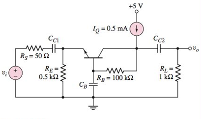
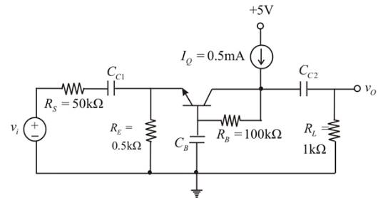
In the common−base circuit shown in Figure P7.70, the transistor parameters are: β = 100 , V B E (on)=0 .7V , V A = , C π = 1 0pF , and C μ = 1 pF . (a) Determine the upper 3dB frequencies corresponding to the input and output portions of the equivalent circuit. (b) Calculate the small−signal midband voltage gain. (c) If a load capacitor C L = 15 pF is connected between the output and ground, determine if the upper 3dB frequency will be dominated by the C L load capacitor or by the transistor characteristics.

Chapter 7, Problem 7.70P, In the commonbase circuit shown in Figure P7.70, the transistor parameters are: =100 , VBE(on)=0.7V
Figure P7.70

(a)

Expert Solution
Check Mark
To determine

The upper 3dB frequencies corresponding to the input and output portions of the equivalent circuit.

Answer to Problem 7.70P

  fHπ=654.7MHz

  fHμ=161MHz

Explanation of Solution

Given:

The given circuit is shown below.

  MICROELECT. CIRCUIT ANALYSIS&DESIGN (LL), Chapter 7, Problem 7.70P , additional homework tip  1

The transistor parameters

  β=100

  VBE(on)=0.7V

  VA=

  Cπ=10pF

and Cμ=1pF

  RS=50Ω

  RE=0.5

  RB=100

  RL=1

  IE=0.5mA

Calculation:

  ICQ=(ββ+1)IEICQ=(100100+1)(0.5)ICQ=0.495mA

Transconductance

  gm=IcQVT

  gm=0.4950.026

  gm=19mA/V

  rπ=βVTICQ

  rπ=(100)(0.026)0.495

  rπ=5.25

For Input Portion:

Time constant,

  τpπ=[(rπ1+β)RERs]Cπ

  =[(5.25101)0.50.05]×103×10×1012

  =0.243×10⁹s

  Upper3dBfrequency,fHπ=12πτpπ=12π(0.243×10⁹)fHπ=654.7MHz

For Output portion:

Time constant,

  τpμ=(RBRL)Cμ

  =(1001)(1×1012)×103

  =0.99×10⁹s

  Upper3dBfrequency,fHμ=12πτpμ=12π(0.99×10⁹)fHμ=161MHz

(b)

Expert Solution
Check Mark
To determine

The small signal mid- band voltage gain

Answer to Problem 7.70P

  Av=9.14

Explanation of Solution

Given:

The given circuit is shown below.

  MICROELECT. CIRCUIT ANALYSIS&DESIGN (LL), Chapter 7, Problem 7.70P , additional homework tip  2

The transistor parameters

  β=100

  VBE(on)=0.7V

  VA=

  Cπ=10pF

and Cμ=1pF

  RS=50Ω

  RE=0.5

  RB=100

  RL=1

  IE=0.5mA

Calculation:

  ICQ=(ββ+1)IEICQ=(100100+1)(0.5)ICQ=0.495mA

Transconductance

  gm=IcQVT

  gm=0.4950.026

  gm=19mA/V

  rπ=βVTICQ

  rπ=(100)(0.026)0.495

  rπ=5.25

  Vo=gmVπ(RBRL)gmVπ+Vnrn+VxRE+vi(Vn)Rs=0Vπ[gm+1rn+1RE+1Rs]=viRs

  Vπ[19+15.25+10.5+10.05]=vi0.05Vπ(41.19)=vi(20)vo=gmVz(RBRL)

  =(19)(0.4856)(1001)vivovi=9.14voltage gain,Av=vovi=9.14Av=9.14

(c)

Expert Solution
Check Mark
To determine

To identify: Whether the upper 3dB frequency will be dominated by the CL load capacitor or by the transistor characteristics.

Answer to Problem 7.70P

Yes, it is dominated by CL

Explanation of Solution

Given:

The given circuit is shown below.

  MICROELECT. CIRCUIT ANALYSIS&DESIGN (LL), Chapter 7, Problem 7.70P , additional homework tip  3

The transistor parameters

  β=100

  VBE(on)=0.7V

  VA=

  Cπ=10pF

and Cμ=1pF

  RS=50Ω

  RE=0.5

  RB=100

  RL=1

  IE=0.5mA

  ICQ=(ββ+1)IEICQ=(100100+1)(0.5)ICQ=0.495mA

Transconductance

  gm=IcQVT

  gm=0.4950.026

  gm=19mA/V

  rπ=βVTICQ

  rπ=(100)(0.026)0.495

  rπ=5.25

Calculation:

For CL=15pF

Time constant,

  τ=CL(RLRB)

  =(15×1012)(1100)103

  =14.85×10⁹s

Upper 3dB frequency, f=12πτ

  =12π(14.85×10⁹)

  =10.7MHz

  f=10.7MHz

Since f<fHμ,3dB frequency dominated by CL

Want to see more full solutions like this?

Subscribe now to access step-by-step solutions to millions of textbook problems written by subject matter experts!
Students have asked these similar questions
1.Select the correct statement(s) regarding frequency modulation (FM) bandwidth.     a.  the more the carrier frequency is allowed to change frequencies (Δf), the smaller the modulated signal bandwidth     b.  the larger the FM index, β, the larger the modulated signal bandwidth     c.  as you increase kvco, you decrease modulated signal bandwidth     d.  all statements are correct     2. Select the correct statement(s) regarding baseband signal modulation.     a.  with modulation, a baseband signal can be moved to a higher frequency thus preventing baseband signal interference     b.  modulation techniques are only required for analog information signals, since digital signals are represented by discrete logical values of “1” and “0”     c.  modulation eliminates the baseband signal’s frequency bandwidth, thus enabling greater efficiencies when transmitting a modulated carrier signal     d.  all statements are correct 3. A…
19)This MCQ QUESTION FROM ANTENNA ENGINEERING course.
Identify how the excessive bandwidth use of FM can be overcome. (Check all that apply.) By using narrowband FM with small deviation ratios By using wideband FM with large deviation ratios By operating in the ultrahigh frequency (UHF) region By operating in the ultralow frequency (ULF) region By operating in the microwave region

Chapter 7 Solutions

MICROELECT. CIRCUIT ANALYSIS&DESIGN (LL)

Ch. 7 - The commonemitter circuit shown in Figure 7.34...Ch. 7 - A bipolar transistor has parameters o=120 ,...Ch. 7 - Prob. 7.9EPCh. 7 - For the circuit in Figure 7.41(a), the parameters...Ch. 7 - A bipolar transistor is biased at ICQ=120A and its...Ch. 7 - For the transistor described in Example 7.9 and...Ch. 7 - The parameters of a bipolar transistor are: o=150...Ch. 7 - The parameters of an nchannel MOSFET are...Ch. 7 - For the circuit in Figure 7.55, the transistor...Ch. 7 - An nchannel MOSFET has parameters Kn=0.4mA/V2 ,...Ch. 7 - An nchannel MOSFET has a unitygain bandwidth of...Ch. 7 - For a MOSFET, assume that gm=1.2mA/V . The basic...Ch. 7 - The transistor in the circuit in Figure 7.60 has...Ch. 7 - Consider the commonbase circuit in Figure 7.64....Ch. 7 - The cascode circuit in Figure 7.65 has parameters...Ch. 7 - Prob. 7.12TYUCh. 7 - For the circuit in Figure 7.72, the transistor...Ch. 7 - Describe the general frequency response of an...Ch. 7 - Describe the general characteristics of the...Ch. 7 - Describe what is meant by a system transfer...Ch. 7 - What is the criterion that defines a corner, or...Ch. 7 - Describe what is meant by the phase of the...Ch. 7 - Describe the time constant technique for...Ch. 7 - Describe the general frequency response of a...Ch. 7 - Sketch the expanded hybrid model of the BJT.Ch. 7 - Prob. 9RQCh. 7 - Prob. 10RQCh. 7 - Prob. 11RQCh. 7 - Sketch the expanded smallsignal equivalent circuit...Ch. 7 - Define the cutoff frequency for a MOSFET.Ch. 7 - Prob. 14RQCh. 7 - Why is there not a Miller effect in a commonbase...Ch. 7 - Describe the configuration of a cascode amplifier.Ch. 7 - Why is the bandwidth of a cascode amplifier...Ch. 7 - Why is the bandwidth of the emitterfollower...Ch. 7 - Prob. 7.1PCh. 7 - Prob. 7.2PCh. 7 - Consider the circuit in Figure P7.3. (a) Derive...Ch. 7 - Consider the circuit in Figure P7.4 with a signal...Ch. 7 - Consider the circuit shown in Figure P7.5. (a)...Ch. 7 - A voltage transfer function is given by...Ch. 7 - Sketch the Bode magnitude plots for the following...Ch. 7 - (a) Determine the transfer function corresponding...Ch. 7 - Consider the circuit shown in Figure 7.15 with...Ch. 7 - For the circuit shown in Figure P7.12, the...Ch. 7 - The circuit shown in Figure 7.10 has parameters...Ch. 7 - The transistor shown in Figure P7.14 has...Ch. 7 - Consider the circuit shown in Figure P7.15. The...Ch. 7 - The transistor in the circuit shown in Figure...Ch. 7 - For the common-emitter circuit in Figure P7.17,...Ch. 7 - The transistor in the circuit in Figure P7.20 has...Ch. 7 - For the circuit in Figure P7.21, the transistor...Ch. 7 - (a) For the circuit shown in Figure P7.22, write...Ch. 7 - Consider the circuit shown in Figure P7.23. (a)...Ch. 7 - The parameters of the transistor in the circuit in...Ch. 7 - A capacitor is placed in parallel with RL in the...Ch. 7 - The parameters of the transistor in the circuit in...Ch. 7 - Prob. D7.27PCh. 7 - The circuit in Figure P7.28 is a simple output...Ch. 7 - Reconsider the circuit in Figure P728. The...Ch. 7 - Consider the circuit shown in Figure P7.32. The...Ch. 7 - The commonemitter circuit in Figure P7.35 has an...Ch. 7 - Consider the commonbase circuit in Figure 7.33 in...Ch. 7 - Prob. 7.39PCh. 7 - The parameters of the transistor in the circuit in...Ch. 7 - In the commonsource amplifier in Figure 7.25(a) in...Ch. 7 - A bipolar transistor has fT=4GHz , o=120 , and...Ch. 7 - A highfrequency bipolar transistor is biased at...Ch. 7 - (a) The frequency fT of a bipolar transistor is...Ch. 7 - The circuit in Figure P7.48 is a hybrid ...Ch. 7 - Consider the circuit in Figure P7.49. Calculate...Ch. 7 - A common-emitter equivalent circuit is shown in...Ch. 7 - For the common-emitter circuit in Figure 7.41(a)...Ch. 7 - For the commonemitter circuit in Figure P7.52,...Ch. 7 - Consider the circuit in Figure P7.52. The resistor...Ch. 7 - The parameters of the circuit shown in Figure...Ch. 7 - The parameters of an nchannel MOSFET are kn=80A/V2...Ch. 7 - Find fT for a MOSFET biased at IDQ=120A and...Ch. 7 - Fill in the missing parameter values in the...Ch. 7 - (a) An nchannel MOSFET has an electron mobility of...Ch. 7 - A commonsource equivalent circuit is shown in...Ch. 7 - Prob. 7.60PCh. 7 - The parameters of an ideal nchannel MOSFET are...Ch. 7 - Figure P7.62 shows the highfrequency equivalent...Ch. 7 - For the FET circuit in Figure P7.63, the...Ch. 7 - The midband voltage gain of a commonsource MOSFET...Ch. 7 - Prob. 7.65PCh. 7 - Prob. 7.67PCh. 7 - The bias voltages of the circuit shown in Figure...Ch. 7 - For the PMOS commonsource circuit shown in Figure...Ch. 7 - In the commonbase circuit shown in Figure P7.70,...Ch. 7 - Repeat Problem 7.70 for the commonbase circuit in...Ch. 7 - In the commongate circuit in Figure P7.72, the...
Knowledge Booster
Background pattern image
Electrical Engineering
Learn more about
Need a deep-dive on the concept behind this application? Look no further. Learn more about this topic, electrical-engineering and related others by exploring similar questions and additional content below.
Similar questions
SEE MORE QUESTIONS
Recommended textbooks for you
Text book image
Introductory Circuit Analysis (13th Edition)
Electrical Engineering
ISBN:9780133923605
Author:Robert L. Boylestad
Publisher:PEARSON
Text book image
Delmar's Standard Textbook Of Electricity
Electrical Engineering
ISBN:9781337900348
Author:Stephen L. Herman
Publisher:Cengage Learning
Text book image
Programmable Logic Controllers
Electrical Engineering
ISBN:9780073373843
Author:Frank D. Petruzella
Publisher:McGraw-Hill Education
Text book image
Fundamentals of Electric Circuits
Electrical Engineering
ISBN:9780078028229
Author:Charles K Alexander, Matthew Sadiku
Publisher:McGraw-Hill Education
Text book image
Electric Circuits. (11th Edition)
Electrical Engineering
ISBN:9780134746968
Author:James W. Nilsson, Susan Riedel
Publisher:PEARSON
Text book image
Engineering Electromagnetics
Electrical Engineering
ISBN:9780078028151
Author:Hayt, William H. (william Hart), Jr, BUCK, John A.
Publisher:Mcgraw-hill Education,
Huffman Codes: An Information Theory Perspective; Author: Reducible;https://www.youtube.com/watch?v=B3y0RsVCyrw;License: Standard Youtube License