
Concept explainers
Videos
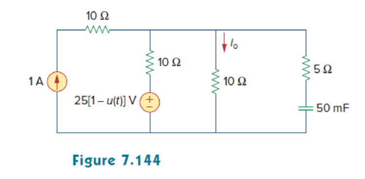
In the circuit of Fig. 7.144, find the value of io for all values of 0 < t.
Find the current
Answer to Problem 80P
The current
Explanation of Solution
Given data:
Refer to Figure 7.144 in the textbook.
The value of capacitance
The source voltage
The current source
Formula used:
Write the general expression to find the complete voltage response for an RC circuit.
Here,
Write the expression to find the time constant for an RC circuit.
Here,
C is the capacitance of the capacitor.
Write the general expression for the unit step function.
Calculation:
The given source voltage is,
Apply the unit step function in equation (3) to equation (4).
For
The given Figure 7.144 is redrawn as shown in Figure 1.
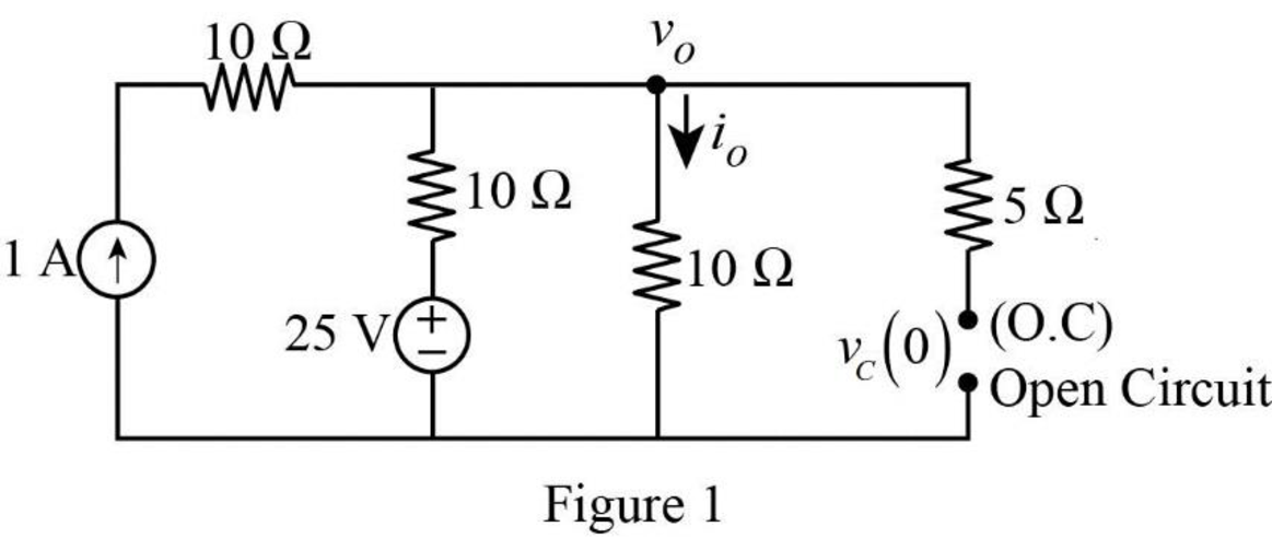
In Figure 1, the capacitor reaches steady state and it will acts as an open circuit. The initial voltage across the capacitor is denoted by
Apply Kirchhoff’s current law at node
Rearrange the equation as follows,
In Figure 1, the initial voltage across the capacitor
For
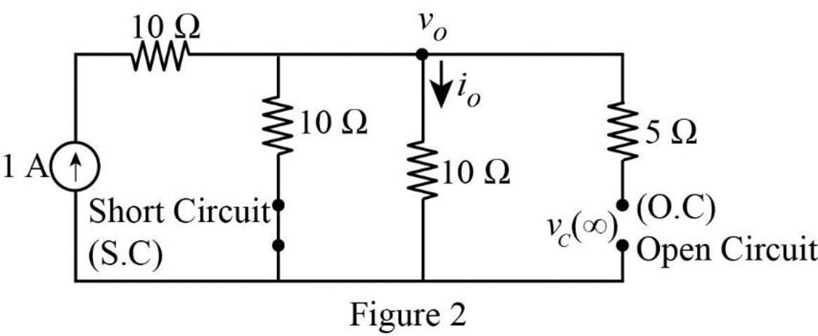
In Figure 2, the voltage source is equal to zero (or a short circuit). Now, the final voltage across the capacitor is represented by
Apply Kirchhoff’s current law at node
Rearrange the equation as follows,
In Figure 2, the final voltage across the capacitor
Figure 3 shows the Thevenin resistance at the capacitor terminal.
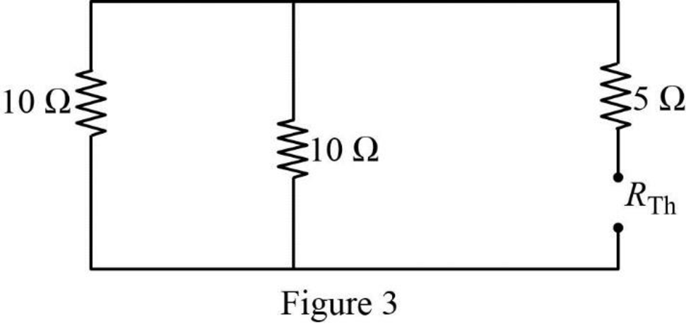
In Figure 3, the Thevenin resistance is calculated as follows.
Substitute
Substitute the units
Substitute
Figure 4 shows the modified circuit diagram.
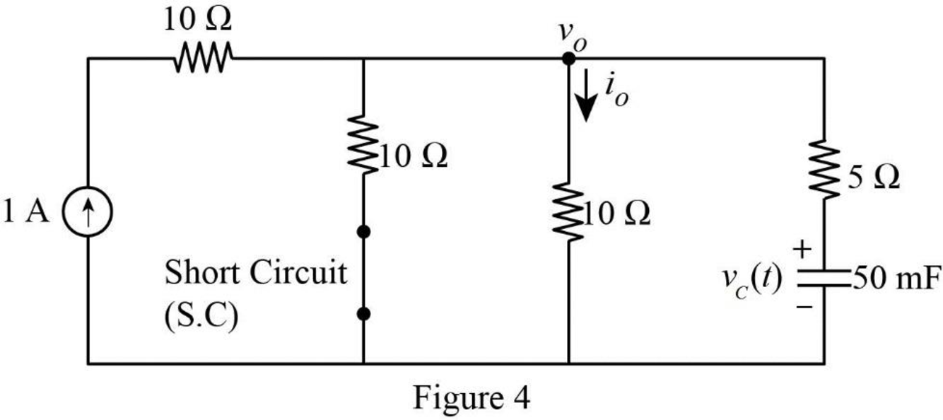
Apply Kirchhoff’s current law at node
Substitute
Reduce the equation as follows,
Therefore, the current
Substitute
Convert the unit A to mA.
Apply the unit step function in equation (3) to equation (6).
PSpice Simulation:
For
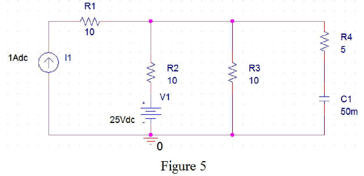
Draw the circuit diagram in PSpice as shown in Figure 5.
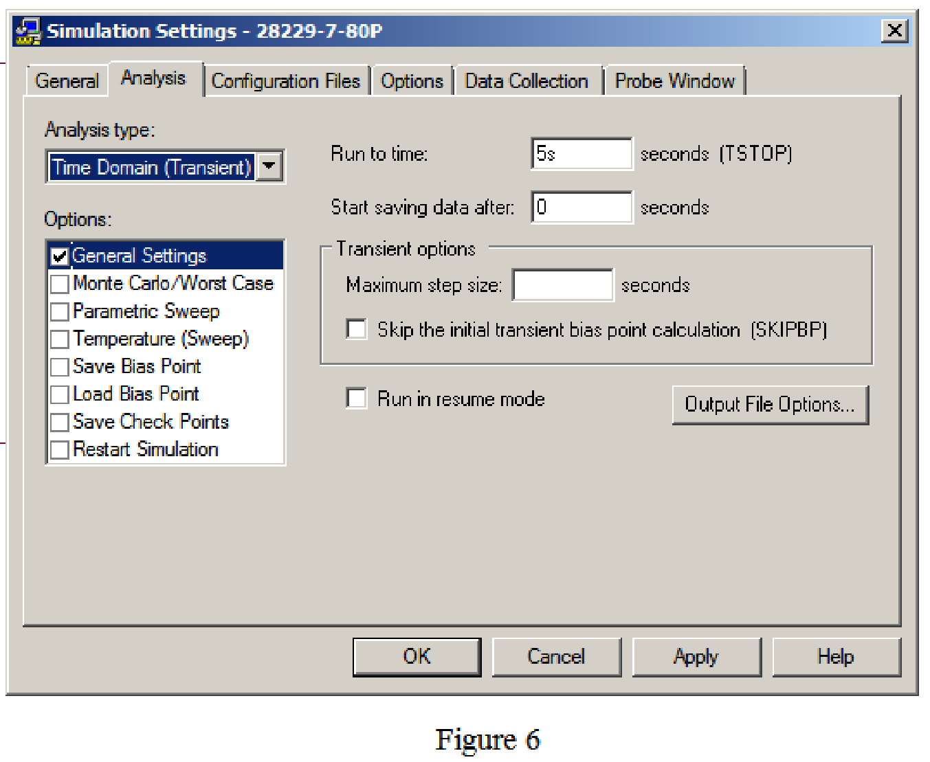
Save the circuit and provide the Simulation Settings as shown in Figure 6.
Now run the simulation and the results will be displayed as shown in Figure 7 by enabling “Enable Bias Voltage Display” icon.
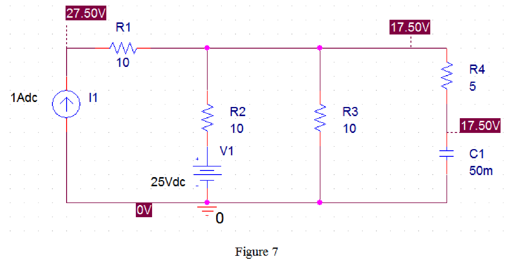
From Figure 7, the initial voltage across the capacitor is 17.5 V.
For
Draw the circuit diagram in PSpice as shown in Figure 8.
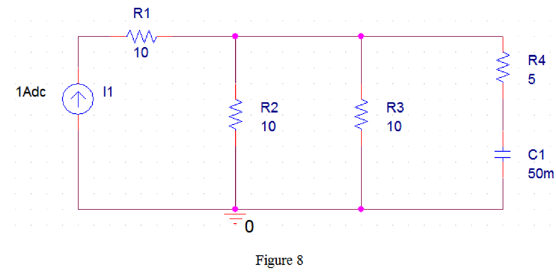
Now run the simulation and the results will be displayed as shown in Figure 8 by enabling “Enable Bias Voltage Display” icon.
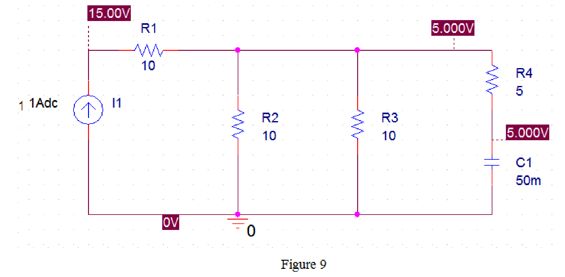
From Figure 9, the final voltage across the capacitor is 5 V.
Draw the circuit diagram in PSpice as shown in Figure 10.
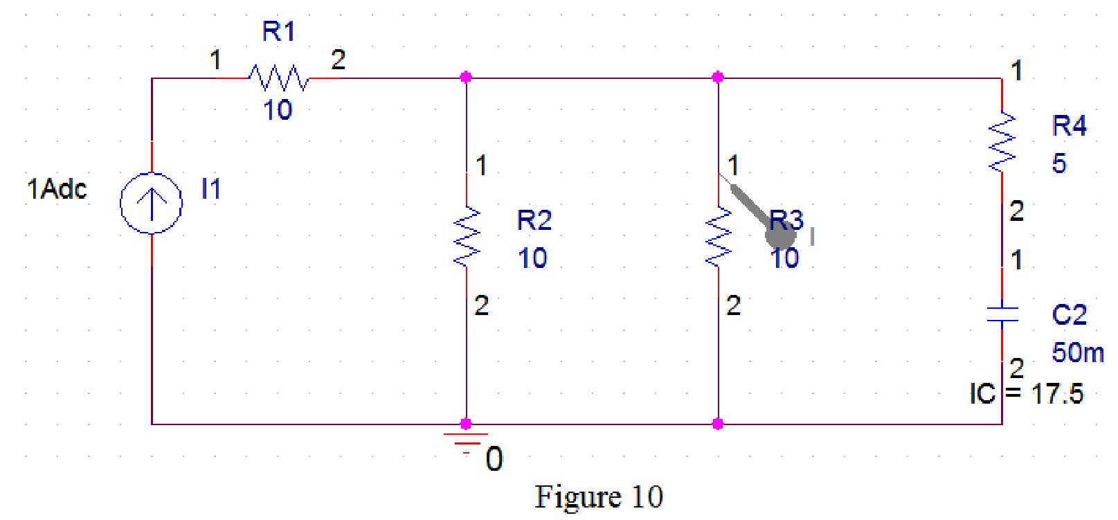
Now run the simulation and the results will be displayed as shown in Figure 11 by enabling “Enable Bias Voltage Display” icon and place the “Current Marker”
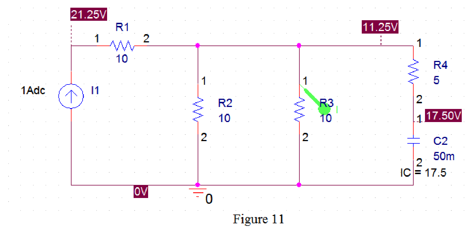
The SCHEMATIC1 dialog box is also opened with simulation result as shown in Figure 12.
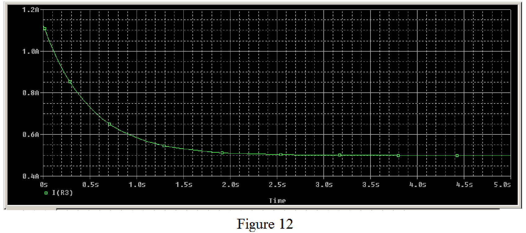
Therefore, the plot of current through the
Conclusion:
Thus, the current
Want to see more full solutions like this?
Chapter 7 Solutions
Connect 2 Semester Access Card for Fundamentals of Electric Circuits


- The switch in the circuit shown in Fig. 7.6 has been closed for a long timebefore it is opened at t=0. Find 4. the percentage of the total energy stored in the 2 H inductor that isdissipated in the 10 Ω resistor.arrow_forwardDesign a circuit that amplifies a 500 mV signal originating from a computer keyboard, so that this signal can be interpreted by the digital circuits found on the motherboard.arrow_forwardhow do i solve the attached electronics question, specifically number 7, 6 given for contextarrow_forward
- An LTI system is considered.The response of the system to x1(t) is y1(t). Then find and sketch the response of the system to x2(t) and x3(t).arrow_forward5) Consider the circuit shown below, in which the switch opens at t=0. Find expressions for v(t), iR(t), and iL(t) for t>0. Assume that iL(t) is zero before the switch opens.arrow_forwardWhat is the time constant (tau) of the circuit? and Find Vc at t=0.05 sec after the circuit is connected to the source.arrow_forward
- For the following circuit obtain: (a) the response v(t) for t>0, (b) the current i(t) through the inductor for t>0.arrow_forwardDesign a digital circuit which has 4 inputs. The output only accepts combinations of 3 inputs.arrow_forwardAn LTI system has an impulse response: h(t) = e'u(t + 2) This system is: Select one: Causal but not stable Not causal but stable Not causal and not stable Causal and stablearrow_forward
 Introductory Circuit Analysis (13th Edition)Electrical EngineeringISBN:9780133923605Author:Robert L. BoylestadPublisher:PEARSON
 Delmar's Standard Textbook Of ElectricityElectrical EngineeringISBN:9781337900348Author:Stephen L. HermanPublisher:Cengage Learning
 Programmable Logic ControllersElectrical EngineeringISBN:9780073373843Author:Frank D. PetruzellaPublisher:McGraw-Hill Education
 Fundamentals of Electric CircuitsElectrical EngineeringISBN:9780078028229Author:Charles K Alexander, Matthew SadikuPublisher:McGraw-Hill Education
 Electric Circuits. (11th Edition)Electrical EngineeringISBN:9780134746968Author:James W. Nilsson, Susan RiedelPublisher:PEARSON
 Engineering ElectromagneticsElectrical EngineeringISBN:9780078028151Author:Hayt, William H. (william Hart), Jr, BUCK, John A.Publisher:Mcgraw-hill Education,