
Concept explainers
Videos
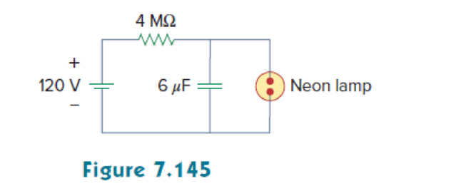
A simple relaxation oscillator circuit is shown in Fig. 7.145. The neon lamp fires when its voltage reaches 75 V and turns off when its voltage drops to 30 V. Its resistance is 120 Ω when on and infinitely high when off.
- (a) For how long is the lamp on each time the capacitor discharges?
- (b) What is the time interval between light flashes?
(a)
Calculate the discharge time of the capacitance when the lamp is on in the given circuit of Figure 7.145.
Answer to Problem 85P
The discharge time of the capacitance is
Explanation of Solution
Given data:
The neon lamp is on when its voltage reaches 75 V and turn off when its voltage drops to 30 V.
The resistance is
Refer to Figure 7.145 in the textbook.
The value of capacitance
Formula used:
Write the general expression to find the complete voltage response for an RC circuit.
Here,
Write the expression to find the time constant for an RC circuit.
Here,
C is the capacitance of the capacitor.
Calculation:
The neon lamp is on when it reaches 75 V. Therefore, the initial capacitor voltage
The neon lamp is off when it drops to 30 V. Therefore, the final capacitor voltage
When the neon lamp on and off, during that time a
Substitute
Substitute the units
Substitute
When the neon lamp is off, the voltage drops to 30 V. That is,
At
Substitute
Taking ln on both sides of the equation.
Rearrange the equation as follows,
Reduce the equation as follows,
Conclusion:
Thus, the discharge time of the capacitance is
(b)
Calculate the time interval between the light flashes.
Answer to Problem 85P
The time interval between the light flashes is
Explanation of Solution
Figure 1 shows the Thevenin resistance at the capacitance terminal.
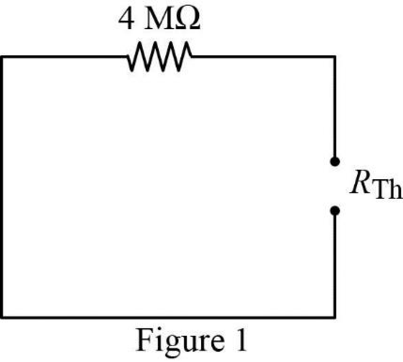
In Figure 1, the Thevenin resistance
Substitute
Substitute the units
At
At
Dividing the equation (6) by (7).
Consider the time interval is,
Substitute
Consider the neon lamp is on when its voltage
Substitute 75 V for
Taking ln on both sides of the equation.
Since, the time interval must be taken as positive value. Therefore,
Conclusion:
Thus, the time interval between the light flashes is
Want to see more full solutions like this?
Chapter 7 Solutions
FUND.OF ELECTRIC CIRCUITS(LL)-W/CONNECT


- The switch in the circuit seen in fig 7.54arrow_forwarddifferential equations applications. A 12-volt battery is connected to a series circuit in which the inductor is 1/2 henry and the resistance is 10 ohms. Determine current i, if the initial current is zero.arrow_forwardIn the circuit below, the switch is closed at t=0 s. It is known that the voltage across the capacitor at t=0.2 s is Vc( t = 0.2 ) = 10.31 V. In this case, what will be the voltage Vc( t = 0.1 ) of the capacitor at t=0.1 s? Calculate.arrow_forward
- 7. 7.27 In the circuit the voltage and current expressions are v=48e−25t V, t≥0;i=12e−25t mA, t≥0+.Find1. a) R.2. b) C.3. c) τ (in milliseconds).4. d) the initial energy stored in the capacitor.5. e) the amount of energy that has been dissipated by the resistor 60ms after the voltage begins to decay.arrow_forwardA capacitor with a capacitance of 32 microfarads is discharged through a resistance of 53 kilo-ohms. How many milliseconds does it take for the voltage to drop to 1/e of its initial value. Here "e" is the base of natural logarithms, about 2.718 .arrow_forwardThe switch in the circuit in fig 7.45arrow_forward
- Two coils of inductance 6 H and 8 H are connected in parallel. If their coefficient of coupling is 0.435, calculate the equivalent inductance of the combination if (a) the mutual inductance assists the self-inductance, and (ii) the mutual inductance opposes the self-inductance.arrow_forwardSolve i(0+) of the inductor 2H The presence of a voltage source indicates an infinite size, which may be stated in the circuit as Vs(t)= δ(t).arrow_forwardDetermine the current in the inductor i (t), for t <0 and t> 0 (see attached image of the circuit)arrow_forward
- kindly help me with this problem thank you so much! Instructions: Evaluate and Show neat, logical, and complete solution.show final answers in four decimal places. 3. A 20 μF capacitor in an audio amplifier produces a voltage drop of 5 V at 1kHz. Find the current passed by the capacitor.arrow_forwardFind Leq between the terminals a,b for the circuits shown below. Assuming the initial energy stored in the inductors is zero.arrow_forwardWhat is the time constant (tau) of the circuit? and Find Vc at t=0.05 sec after the circuit is connected to the source.arrow_forward
 Introductory Circuit Analysis (13th Edition)Electrical EngineeringISBN:9780133923605Author:Robert L. BoylestadPublisher:PEARSON
 Delmar's Standard Textbook Of ElectricityElectrical EngineeringISBN:9781337900348Author:Stephen L. HermanPublisher:Cengage Learning
 Programmable Logic ControllersElectrical EngineeringISBN:9780073373843Author:Frank D. PetruzellaPublisher:McGraw-Hill Education
 Fundamentals of Electric CircuitsElectrical EngineeringISBN:9780078028229Author:Charles K Alexander, Matthew SadikuPublisher:McGraw-Hill Education
 Electric Circuits. (11th Edition)Electrical EngineeringISBN:9780134746968Author:James W. Nilsson, Susan RiedelPublisher:PEARSON
 Engineering ElectromagneticsElectrical EngineeringISBN:9780078028151Author:Hayt, William H. (william Hart), Jr, BUCK, John A.Publisher:Mcgraw-hill Education,