
Concept explainers
Videos
For the circuit in Fig. 7.100,
v = 90e−50t V
and
i = 30e−50t A, t > 0
- (a) Find L and R.
- (b) Determine the time constant.
- (c) Calculate the initial energy in the inductor.
- (d) What fraction of the initial energy is dissipated in 10 ms?
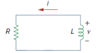
Figure 7.100
(a)
Find the value of resistance R and inductance L in the Figure 7.100.
Answer to Problem 20P
The value of resistance R in the circuit is
Explanation of Solution
Given data:
The voltage
The current
Formula used:
Write the expression to find the voltage across the inductor for the given circuit.
Here,
L is the inductance of the inductor.
Write the expression to find the time constant for RL circuit.
Here,
R is the resistance of the resistor.
Write the general expression to find the voltage response in the RL Circuit.
Here,
Calculation:
Substitute
Rearrange the equation as follows,
Convert the unit H to mH.
Compare the given voltage
Rearrange the equation (4) to find the time constant
Substitute
Rearrange the equation (5) to find the resistance R in ohms.
Conclusion:
Thus, the value of resistance R in the circuit is
(b)
Find the time constant
Answer to Problem 20P
The time constant
Explanation of Solution
Given data:
Refer to part (a).
The value of resistance R is
The value of inductance L is
Calculation:
Substitute
Substitute the units
Convert the unit s to ms.
Conclusion:
Thus, the time constant
(c)
Find the value of initial energy stored in the inductor.
Answer to Problem 20P
The value of initial energy stored in the inductor is
Explanation of Solution
Given data:
Refer to part (a).
The value of inductance L is
Formula used:
Write the expression to find the energy stored in the inductor.
Here,
Calculation:
The given current is,
The initial current in the RL circuit at
Substitute
Conclusion:
Thus, the value of initial energy stored in the inductor is
(d)
Find the fraction of the energy dissipated in the first 10 ms.
Answer to Problem 20P
The fraction of the energy dissipated in the first 10 ms is
Explanation of Solution
Given data:
Refer to part (c).
The value of initial energy w stored in the inductor is
Formula used:
Write the expression to find the energy stored in the inductor.
Calculation:
The given current is,
The current in the RL circuit at
Substitute
The fraction of the energy dissipated in the first 10 ms is calculated as follows.
Substitute
Conclusion:
Thus, the fraction of the energy dissipated in the first 10 ms is
Want to see more full solutions like this?
Chapter 7 Solutions
FUND.OF ELECTRIC CIRCUITS(LL)-W/CONNECT


- In the circuit below, the switch is closed at t=0 s. It is known that the voltage across the capacitor at t=0.2 s is Vc( t = 0.2 ) = 10.31 V. In this case, what will be the voltage Vc( t = 0.1 ) of the capacitor at t=0.1 s? Calculate.arrow_forwardFind Leq between the terminals a,b for the circuits shown below. Assuming the initial energy stored in the inductors is zero.arrow_forwardThe current (I) flowing in a circuit containing a capacitor that is discharging changes with time (t) according to the equation:I = Io e-t/(CR)A circuit contains a capacitor of 30 x 10-6 F in series with a resistance of 4.7 x 10 5 Ω. If the initial current is 3.5A , calculate the current after 15 s.arrow_forward
- A 20μF capacitor is subjected to a voltage pulse having a duration of 1 s. The pulse is described by the following equations: vc(t)={30t2 V,0≤t≤0.5 s;30(t−1)2 V,0.5 s≤t≤1 s;0elsewhere. Sketch the current pulse that exists in the capacitor during the 1 s interval.arrow_forwardFor the circuit shown, calculate 1. the initial energy stored in the capacitors; 2. the final energy stored in the capacitors; 3. the total energy delivered to the black box; 4. the percentage of the initial energy stored that is delivered to the black box; and 5. the time, in milliseconds, it takes to deliver 7.5 mJ to the black box.arrow_forwardThe switch in the circuit shown in Fig. 7.6 has been closed for a long timebefore it is opened at t=0. Find 3. vo(t) for t≥0+,arrow_forward
- *Assume that at the instant the 2 A dc current source is applied to the circuit in (Figure 1), the initial current in the 25 mH inductor is 1 A, and the initial voltage on the capacitor is 50 V (positive at the upper terminal).* Pt A. Find the expression for iL(t) for t≥0 if R equals 12.5 Ωarrow_forward7. 7.27 In the circuit the voltage and current expressions are v=48e−25t V, t≥0;i=12e−25t mA, t≥0+.Find1. a) R.2. b) C.3. c) τ (in milliseconds).4. d) the initial energy stored in the capacitor.5. e) the amount of energy that has been dissipated by the resistor 60ms after the voltage begins to decay.arrow_forwardFor the circuit shown Vs = 12 V, R1 = 11 kΩ, R2 = 23 kΩ, R3 = 32 kΩ, C = 3.8 μF, L = 84 mH. If the switch opens after a long time, determine the time after t = 0 that it takes the capacitor to discharge.arrow_forward
- A 100µF capacitor is connected in series with a 150volt voltmeter that has a resistance of 1,000 ohms per volt. Calculate the reading of the voltmeter at the instant when t equals the time constant following the closing if the switch that impresses 120volts on the circuit.arrow_forwardThe current in a 20 mH inductor is known to be i=40 mA,t≤0; i=A1e−10,000t+A2e−40.000tA,t≥0. The voltage across the inductor (passive sign convention) is 28 V at t=0. 1. Find the expression for the voltage across the inductor for t>0. 2. Find the time, greater than zero, when the power at the terminals of the inductor is zero.arrow_forwarddifferential equations applications. A 12-volt battery is connected to a series circuit in which the inductor is 1/2 henry and the resistance is 10 ohms. Determine current i, if the initial current is zero.arrow_forward
 Introductory Circuit Analysis (13th Edition)Electrical EngineeringISBN:9780133923605Author:Robert L. BoylestadPublisher:PEARSON
 Delmar's Standard Textbook Of ElectricityElectrical EngineeringISBN:9781337900348Author:Stephen L. HermanPublisher:Cengage Learning
 Programmable Logic ControllersElectrical EngineeringISBN:9780073373843Author:Frank D. PetruzellaPublisher:McGraw-Hill Education
 Fundamentals of Electric CircuitsElectrical EngineeringISBN:9780078028229Author:Charles K Alexander, Matthew SadikuPublisher:McGraw-Hill Education
 Electric Circuits. (11th Edition)Electrical EngineeringISBN:9780134746968Author:James W. Nilsson, Susan RiedelPublisher:PEARSON
 Engineering ElectromagneticsElectrical EngineeringISBN:9780078028151Author:Hayt, William H. (william Hart), Jr, BUCK, John A.Publisher:Mcgraw-hill Education,