
Engineering Mechanics: Statics & Dynamics (14th Edition)
14th Edition
ISBN: 9780133915426
Author: Russell C. Hibbeler
Publisher: PEARSON
expand_more
expand_more
format_list_bulleted
Videos
Textbook Question
Chapter 7.1, Problem 25P
Determine the normal force, shear force, and moment in the beam at sections passing through points D and E. Point E is just to the right of the 3-kip load.
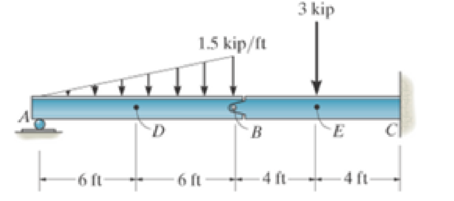
Prob. 7-25
Expert Solution & Answer

Trending nowThis is a popular solution!

Students have asked these similar questions
The aluminum strut has a cross-sectional area in the form of a cross. It is subjected tothe Moment M = 8 KN.m. (i) Determine the bending stress acting at points A and B; (ii)Determine the maximum bending stress in the beam and sketch a three dimensional view of thestress distribution acting over the entire cross-sectional area.
The cantilevered beam has a circular cross section. If it supports a force P at its end, determine its radius y as a function of x so that it is subjected to a constant maximum bending stress sallow throughout its length.
7-59: Draw the shear and moment diagrams for the beam.
Chapter 7 Solutions
Engineering Mechanics: Statics & Dynamics (14th Edition)
Ch. 7.1 - In each case, calculate the reaction at A and then...Ch. 7.1 - Determine the normal force, shear force, and...Ch. 7.1 - Determine the normal force, shear force, and...Ch. 7.1 - Determine the normal force, shear force, and...Ch. 7.1 - Determine the normal force, shear force, and...Ch. 7.1 - Determine the normal force, shear force, and...Ch. 7.1 - Determine the normal force, shear force, and...Ch. 7.1 - Determine the shear force and moment at points C...Ch. 7.1 - Determine the internal normal force and shear...Ch. 7.1 - Two beams are attached to the column such that...
Ch. 7.1 - The beam weighs 280 lb/ft. Determine the internal...Ch. 7.1 - The pliers are used to grip the tube at B. If a...Ch. 7.1 - Determine the distance a as a fraction of the...Ch. 7.1 - Determine the internal shear force and moment...Ch. 7.1 - Determine the internal shear force and moment...Ch. 7.1 - Determine the normal force, shear force, and...Ch. 7.1 - The cable will fail when subjected to a tension of...Ch. 7.1 - Determine the internal normal force, shear force,...Ch. 7.1 - Determine the distance a between the bearings in...Ch. 7.1 - Determine the internal normal force, shear force,...Ch. 7.1 - The shaft is supported by a journal bearing at A...Ch. 7.1 - Determine the internal normal force, shear force,...Ch. 7.1 - Determine the internal normal force, shear force,...Ch. 7.1 - The cantilevered rack is used to support each end...Ch. 7.1 - Determine the internal normal force, shear force,...Ch. 7.1 - Determine the internal normal force, shear force,...Ch. 7.1 - Rod AB is fixed to a smooth collar D, which slides...Ch. 7.1 - Determine the internal normal force, shear force,...Ch. 7.1 - Determine the internal normal force, shear force,...Ch. 7.1 - Determine the internal normal force, shear force,...Ch. 7.1 - Determine the ratio of a/b for which the shear...Ch. 7.1 - Determine the normal force, shear force, and...Ch. 7.1 - Determine the internal normal force, shear force,...Ch. 7.1 - Determine the internal normal force, shear force,...Ch. 7.1 - Determine the internal normal force, shear force,...Ch. 7.1 - Determine the normal force, shear force, and...Ch. 7.1 - Determine the normal force, shear force, and...Ch. 7.1 - Determine the internal normal force, shear force,...Ch. 7.1 - Determine the internal normal force, shear force,...Ch. 7.1 - Determine the internal normal force, shear force,...Ch. 7.1 - Determine the internal normal force, shear force,...Ch. 7.1 - The strongback or lifting beam is used for...Ch. 7.1 - Determine the internal normal force, shear force,...Ch. 7.1 - Determine the internal normal force, shear force,...Ch. 7.1 - Determine the internal normal force, shear force,...Ch. 7.1 - The distributed loading W = W0 sin , measured per...Ch. 7.1 - Solve Prob. 7-39 for = 120. Probs. 739/40Ch. 7.1 - Determine the x, y. z components of force and...Ch. 7.1 - Determine the x, y, z components of force and...Ch. 7.1 - Determine the x, y, z components of internal...Ch. 7.1 - Determine the x, y. z components of internal...Ch. 7.2 - Determine the shear and moment as a function of x,...Ch. 7.2 - Determine the shear and moment as a function of x,...Ch. 7.2 - Determine the shear and moment as a function of x,...Ch. 7.2 - Determine the shear and moment as a function of x,...Ch. 7.2 - Determine the shear and moment as a function of x,...Ch. 7.2 - Determine the shear and moment as a function of x,...Ch. 7.2 - Draw the shear and moment diagrams for the shaft...Ch. 7.2 - Draw the shear and moment diagrams for the beam...Ch. 7.2 - Draw the shear and moment diagrams for the beam...Ch. 7.2 - Draw the shear and moment diagrams for the...Ch. 7.2 - Draw the shear and moment diagrams of the beam (a)...Ch. 7.2 - If L = 9 m, the beam will fail when the maximum...Ch. 7.2 - Draw the shear and moment diagrams for the beam....Ch. 7.2 - Draw the shear and moment diagrams for the beam....Ch. 7.2 - Draw the shear and bending-moment diagrams for the...Ch. 7.2 - The shaft is supported by a smooth thrust bearing...Ch. 7.2 - Draw the shear and moment diagrams for the beam....Ch. 7.2 - Draw the shear and moment diagrams for the beam....Ch. 7.2 - Draw the shear and moment diagrams for the...Ch. 7.2 - Draw the shear and bending-moment diagrams for...Ch. 7.2 - Draw the shear and moment diagrams for the beam....Ch. 7.2 - The shaft is supported by a smooth thrust bearing...Ch. 7.2 - Draw the shear and moment diagrams for the beam....Ch. 7.2 - The beam will fail when the maximum internal...Ch. 7.2 - Prob. 63PCh. 7.2 - Prob. 64PCh. 7.2 - Prob. 65PCh. 7.2 - Draw the shear and moment diagrams for the beam....Ch. 7.2 - Determine the internal normal force, shear force,...Ch. 7.2 - The quarter circular rod lies in the horizontal...Ch. 7.2 - Express the internal shear and moment components...Ch. 7.3 - Draw the shear and moment diagrams for the beam....Ch. 7.3 - Draw the shear and moment diagrams for the beam....Ch. 7.3 - Draw the shear and moment diagrams for the beam....Ch. 7.3 - Draw the shear and moment diagrams for the beam....Ch. 7.3 - Draw the shear and moment diagrams for the beam....Ch. 7.3 - Draw the shear and moment diagrams for the beam....Ch. 7.3 - Draw the shear and moment diagrams for the beam....Ch. 7.3 - Draw the shear and moment diagrams for the beam....Ch. 7.3 - Draw the shear and moment diagrams for the beam....Ch. 7.3 - Draw the shear and moment diagrams for the...Ch. 7.3 - Draw the shear and moment diagrams for the beam....Ch. 7.3 - Draw the shear and moment diagrams for the beam....Ch. 7.3 - Draw the shear and moment diagrams for the beam....Ch. 7.3 - Draw the shear and moment diagrams for the beam....Ch. 7.3 - Draw the shear and moment diagrams for the beam....Ch. 7.3 - Draw the shear and moment diagrams for the shaft....Ch. 7.3 - Draw the shear and moment diagrams for the beam....Ch. 7.3 - The beam consists of three segments pin connected...Ch. 7.3 - Draw the shear and moment diagrams for the beam....Ch. 7.3 - Draw the shear and moment diagrams for the beam....Ch. 7.3 - Draw the shear and moment diagrams for the beam....Ch. 7.3 - Draw the shear and moment diagrams for the beam....Ch. 7.3 - Draw the shear and moment diagrams for the beam....Ch. 7.3 - Draw the shear and moment diagrams for the beam....Ch. 7.3 - Draw the shear and moment diagrams for the beam....Ch. 7.3 - Draw the shear and moment diagrams for the beam....Ch. 7.3 - Draw the shear and moment diagrams for the beam....Ch. 7.3 - Draw the shear and moment diagrams for the beam....Ch. 7.3 - Draw the shear and moment diagrams for the beam....Ch. 7.3 - Draw the shear and moment diagrams for the beam....Ch. 7.4 - The cable supports the three loads shown....Ch. 7.4 - Prob. 95PCh. 7.4 - Determine the tension in each segment of the cable...Ch. 7.4 - Prob. 97PCh. 7.4 - The cable supports the loading shown. Determine...Ch. 7.4 - The cable supports the three loads shown....Ch. 7.4 - The cable supports the three loads shown....Ch. 7.4 - Determine the force P needed to hold the cable in...Ch. 7.4 - Determine the maximum uniform loading w, measured...Ch. 7.4 - The cable is subjected to a uniform loading of w =...Ch. 7.4 - The cable AB is subjected to a uniform loading of...Ch. 7.4 - If x = 2 ft and the crate weighs 300 lb, which...Ch. 7.4 - If yB = 1.5 ft. determine the largest weight of...Ch. 7.4 - The cable supports a girder which weighs 850...Ch. 7.4 - The cable is subjected to a uniform loading of w =...Ch. 7.4 - If the pipe has a mass per unit length of 1500...Ch. 7.4 - Prob. 110PCh. 7.4 - Prob. 111PCh. 7.4 - The cable will break when the maximum tension...Ch. 7.4 - Prob. 113PCh. 7.4 - The power transmission cable weighs 10 lb/fl. If...Ch. 7.4 - Prob. 115PCh. 7.4 - Prob. 116PCh. 7.4 - Prob. 117PCh. 7.4 - Prob. 118PCh. 7.4 - Show that the deflection curve of the cable...Ch. 7.4 - Prob. 120PCh. 7.4 - Prob. 121PCh. 7.4 - Prob. 122PCh. 7.4 - A cable has a weight of 5 lb/ft. If it can span...Ch. 7.4 - The 10 kg/m cable is suspended between the...Ch. 7.4 - Determine the internal normal force, shear force,...Ch. 7.4 - Prob. 2RPCh. 7.4 - Prob. 3RPCh. 7.4 - Prob. 4RPCh. 7.4 - Draw the shear and moment diagrams for the beam....Ch. 7.4 - A chain is suspended between points at the same...
Knowledge Booster


Learn more about
Need a deep-dive on the concept behind this application? Look no further. Learn more about this topic, mechanical-engineering and related others by exploring similar questions and additional content below.Similar questions
- A) Determine the internal shear force (in N) in section S-S B) Determine the intermal normal force (in N) Section S-S C) Determine the internal bending moment (N-m) Secion S-Sarrow_forwardDraw the shear and moment diagrams for the shaft. The bearings at A and B exert only vertical reactions on the shaft. Also, express the shear and moment in the shaft as a function of x within the region 125 mm 6 x 6 725 mm.arrow_forwardIf the beam is subjected to a bending moment of M = 5 kN-m, determine the bending stress developed at point A and sketch the result on a differential element at this point. Show free body diagram.arrow_forward
- Sketch the intensity of the shear-stress distribution acting over the beam’s cross-sectional area, and determine the resultant shear force acting on the segment AB. The shear force acting at the section is V = 35 kip. Show that INA = 872.49 in4.arrow_forwardConstruct the shear force and bending moment diagram with the help of free body diagrams (value of Y=7)arrow_forwardDraw the shear and moment diagrams for the shaft and determine the shear and moment throughout the shaft as a function of x for 0 … x 6 3 ft, 3 ft 6 x 6 5 ft, and 5 ft 6 x 6 6 ft. The bearings at A and B exert only vertical reactions on the shaft.arrow_forward
- Determine the normal force, shear force, and moment at points C and D in the beam.arrow_forwardThe beam has a rectangular cross section with a width of 8 in. and a height of 14 in. Determine the absolute maximum bending stress in the beam.arrow_forwardIf the beam in Prob. 6–28 has a rectangular cross section with a width b and a height h, determine the absolute maximum bending stress in the beam.arrow_forward
- Determine the magnitude of the resultant internal normal force, shear force and bending moment on the cross section at point Darrow_forward7.65 The shaft is supported by a smooth thrust bearing at A and a smooth journal bearing at B. Identify the shear and moment diagrams for the shaft. Draw the sheer and moment diagramarrow_forwardThe 80-lb weight is dropped from rest at a height h = 4 ft onto the end of the A-36 steel W6 * 12 beam. Determine the maximum bending stress developed in the beam.arrow_forward
arrow_back_ios
SEE MORE QUESTIONS
arrow_forward_ios
Recommended textbooks for you
 Elements Of ElectromagneticsMechanical EngineeringISBN:9780190698614Author:Sadiku, Matthew N. O.Publisher:Oxford University Press
 Mechanics of Materials (10th Edition)Mechanical EngineeringISBN:9780134319650Author:Russell C. HibbelerPublisher:PEARSON
 Thermodynamics: An Engineering ApproachMechanical EngineeringISBN:9781259822674Author:Yunus A. Cengel Dr., Michael A. BolesPublisher:McGraw-Hill Education
 Control Systems EngineeringMechanical EngineeringISBN:9781118170519Author:Norman S. NisePublisher:WILEY
 Mechanics of Materials (MindTap Course List)Mechanical EngineeringISBN:9781337093347Author:Barry J. Goodno, James M. GerePublisher:Cengage Learning
 Engineering Mechanics: StaticsMechanical EngineeringISBN:9781118807330Author:James L. Meriam, L. G. Kraige, J. N. BoltonPublisher:WILEY
Elements Of Electromagnetics
Mechanical Engineering
ISBN:9780190698614
Author:Sadiku, Matthew N. O.
Publisher:Oxford University Press
Mechanics of Materials (10th Edition)
Mechanical Engineering
ISBN:9780134319650
Author:Russell C. Hibbeler
Publisher:PEARSON
Thermodynamics: An Engineering Approach
Mechanical Engineering
ISBN:9781259822674
Author:Yunus A. Cengel Dr., Michael A. Boles
Publisher:McGraw-Hill Education
Control Systems Engineering
Mechanical Engineering
ISBN:9781118170519
Author:Norman S. Nise
Publisher:WILEY
Mechanics of Materials (MindTap Course List)
Mechanical Engineering
ISBN:9781337093347
Author:Barry J. Goodno, James M. Gere
Publisher:Cengage Learning
Engineering Mechanics: Statics
Mechanical Engineering
ISBN:9781118807330
Author:James L. Meriam, L. G. Kraige, J. N. Bolton
Publisher:WILEY
An Introduction to Stress and Strain; Author: The Efficient Engineer;https://www.youtube.com/watch?v=aQf6Q8t1FQE;License: Standard YouTube License, CC-BY