
Concept explainers
Videos
A solenoid is an arrangement of many current loops placed together as shown below. The current through each loop is the same and is in the direction shown.
Obtain or draw an enlargement of the figure.
1. At each of the labeled points, draw a vector to indicate the direction and magnitude of the magnetic field. Use the principle of superposition in determine your answer.
2. Sketch magnetic field lines on the enlargement.
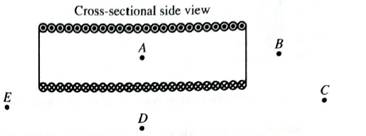
Describe the magnetic field near the center of the solenoid.
3. How does the field of the solenoid a points A-E compare with that of a bar magnet (both inside and outside?
Which end of the solenoid corresponds to a north pole? Which end corresponds to a south pole?
4. How would the magnetic field at any point within the solenoid be affected by the following changes? Explain your reasoning in each case.
• The current through each coil of the solenoid is increased by a factor of two.
• The number of coils in each unit length of the solenoid is increased by a factor of two, with the current through each coil remaining the same.

Trending nowThis is a popular solution!

Learn your wayIncludes step-by-step video

Chapter 7 Solutions
Tutorials in Introductory Physics
Additional Science Textbook Solutions
Conceptual Physics (12th Edition)
University Physics Volume 1
The Cosmic Perspective
Physics (5th Edition)
Cosmic Perspective Fundamentals
College Physics (10th Edition)


- The figure below shows the cross-sections of the two infinite straight co-axial conductors. The conducting domains in the figure are represented by shaded regions. The inner conductor carries current I that is flowing into the page, while the outer conductor carries current I that is flowing out of the page. If the given currents are uniformly distributed over their corresponding conducting bodies, what is the magnetic field vector at point (0, +r), where b < r < c?arrow_forwardThese dots representa magnetic field that is perpendicular to the plane of the paper, and is pointing out of the paper, toward you. The field strength is 1.2 T. A charged particle enters the field as shown. Its speed is 3.0 x 10⁶m/s, and its mass is 10-25kg. (see image attached: enters from left, and circles downward) a) If the radius of the circle in which the particle moves is 0.80 cm, what is the magnitude of the particle’s charge? b) What is the magnitude of the force that the particle feels? c) Is the particle positively or negatively charged?arrow_forwardConsider the two current-carrying wires in the figure. On the left is a long, straight wire carrying current I1. In the same plane, there is a rectangular loop, which carries a current I2. The dimensions of the rectangular loop are shown in the figure, and the left side of the loop is a distance c from the wire. What are the magnitude and direction of the net force exerted on the loop by the magnetic field created by the wire? (Use any variable or symbol stated above along with the following as necessary: ?0, ℓ, and a.)arrow_forward
- What is the magnetic field at the position of the dot in the following figure (Figure 1)? Give your answer as a vector. Express your answer in terms of the unit vectors i^, j^, and k^.arrow_forward1. There are three parallel wires Ꚛ Ꚛ ʘ. In the left and the center wires current directed to the page, and in the right - out the page. If the left and the right wires are fixed, what is the direction of the force on the middle wire? 2. What conclusion can be drawn about the relation between magnetic force and currents? 3. What is the theoretical slope of the graph F vs. IA*IB and does it agree with the simulation? 4. What conclusion can you draw about the relation between magnetic force and distance? 5. What is the theoretical slope of the graph F vs 1/R and does it agree with the simulation one?arrow_forwardUse the picture What is the magnetic field at point p3? (Answer with x,y,z components)arrow_forward
- Two parallel wires carry currents as shown in the diagram to the right. What is the direction of the force acting on wire II? Explain the reasoning behind your selection in detail.A) leftB) rightC) out of the pageD) into the pageE) clockwisearrow_forwardDetermine the magnetic field direction that causes the charged particle shown in (Figure 1) (a) to experience the indicated magnetic force. Match the words in the left column to the appropriate blanks in the sentences on the right.arrow_forwardTwo very long wires are parallel to each other separated by a distance d. The same current flows through each wire but in opposite directions. See the arrows in the diagram. Let I = 1 Amp and d = 0.1 meter. a) What is the direction of the net magnetic field due to the two, long wires in the space between the wires? Explain your answer. b) Calculate the magnitude of the net field at point P, which is half-way between the wires. c) Calculate the magnitude of the magnetic force per unit length due to wire #1 on #2. d) Determine the direction of the force calculated in part (c) and explain your answer.arrow_forward
- Two wires lie perpendicular to the plane of the paper and equal electric currents pass through the paper in the directions shown. Point P is equidstant from the two wires. a) Construct a vector diagram showing the direction of the resultant magnetic field at point P due to currents in these wires. Explain your reasoning. b) If the currents in both wires were instead directed into the plane of the page (such that the current moved away from us), show the resultant magentic field at point P.arrow_forwardFor the moment please disregard the moving charge off to the right. The diagram above shows segments of two long straight wires, carrying currents I_1 = 1.50 A and I_2 = 1.69 A respectively. The distance between the wires is 4.47 cm. What is the force on a 1.60-cm segment of wire #2 due to the magnetic field from wire #1?arrow_forwardUse Lenz's law to answer the following questions concerning the direction of induced currents. Express your answers in terms of the letter labels a and b in each part of the figure below. (a) What is the direction of the induced current in the resistor R in Figure a when the bar magnet is moved to the left? (b) What is the direction of the current induced in the resistor R after the switch S in Figure b is closed? (c) What is the direction of the induced current in the resistor R when the current I in Figure c decreases rapidly to zero?arrow_forward
 College PhysicsPhysicsISBN:9781305952300Author:Raymond A. Serway, Chris VuillePublisher:Cengage Learning
 University Physics (14th Edition)PhysicsISBN:9780133969290Author:Hugh D. Young, Roger A. FreedmanPublisher:PEARSON
 Introduction To Quantum MechanicsPhysicsISBN:9781107189638Author:Griffiths, David J., Schroeter, Darrell F.Publisher:Cambridge University Press
 Physics for Scientists and EngineersPhysicsISBN:9781337553278Author:Raymond A. Serway, John W. JewettPublisher:Cengage Learning
 Lecture- Tutorials for Introductory AstronomyPhysicsISBN:9780321820464Author:Edward E. Prather, Tim P. Slater, Jeff P. Adams, Gina BrissendenPublisher:Addison-Wesley
 College Physics: A Strategic Approach (4th Editio...PhysicsISBN:9780134609034Author:Randall D. Knight (Professor Emeritus), Brian Jones, Stuart FieldPublisher:PEARSON