
Videos
The shaft is supported by a smooth thrust bearing at A and a smooth journal bearing at B. Draw the shear and moment diagrams for the shaft (a) in terms of the parameters shown; (b) set w = 500 lb/ft, L = 10ft.
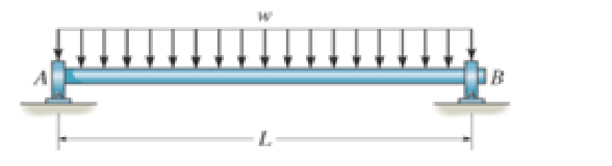
Prob. 7–54

Learn your wayIncludes step-by-step video

Chapter 7 Solutions
Engineering Mechanics: Statics, Student Value Edition; Modified Mastering Engineering with Pearson eText -- Standalone Access Card -- for Engineering Mechanics: Statics (14th Edition)
Additional Engineering Textbook Solutions
Automotive Technology: Principles, Diagnosis, And Service (6th Edition) (halderman Automotive Series)
Automotive Technology: Principles, Diagnosis, and Service (5th Edition)
Statics and Mechanics of Materials (5th Edition)
Engineering Mechanics: Statics & Dynamics (14th Edition)
Applied Fluid Mechanics (7th Edition)
Engineering Mechanics: Dynamics (14th Edition)


- 7-11. The shaft is supported by a journal bearing at A and a thrust bearing at B. Determine the normal force, shear force, and moment at a section passing through (a) point C, which is just to the right of the bearing at A, and (b) point D, which is just to the left of the 3000-lb force. 3000 lb 2500 lb 75 lb/ft B 6 ft- -12 ft- 2 ftarrow_forwardThe shaft is supported by a smooth thrust bearing at A and a smooth journal bearing at B. Take: d1 = 1 m, d2 =1 m, d3 = 1 m, d4 = 1.2 m, d5 = 1.4 m, F1 = 691 N/m, and F2 = 1,189 N. Determine the bending moment (Mc) acting on the cross section at C in N-m. Hint: consider the sign convention for internal loods. F1 В + di d2 d3 d4 ds F2arrow_forwardThe shaft is supported by a smooth thrust bearing at A and smooth journal bearing at C. If d = 3 in., determine the absolute maximum bending stress in the shaft.arrow_forward
- 7-11 Determine the internal normal force, shear force, and moment at points C and D of the beam. 60 lb/ft A -12 ft- -15 ft- C 40 lb/ft -B D OT -5 ft- -10 ft- 690 lb 13 12 5arrow_forwardTHEMAGI *7-48. Draw the shear and moment diagrams for the cantilevered beam. A -5 ft- 800 lb-ft B Prob. 7-48 5 ft- 100 lb Carrow_forwardDetermine the equations of bending moment and shear force for 0arrow_forwardDraw the shear and moment diagrams for the shaft. Let P = 9 kN, a = 2 m, and L = 6 m. There is a thrust bearing at A and a journal bearing at B. P A Answer: Full solution posted on Drive L Barrow_forward7-63. The jib crane supports a load of 750 lb. If the boom AB has a uniform weight of 60lb/ft, draw the shear and moment diagrams for the boom. Problem 7-63 A 7 ft 3 ft- Barrow_forwardDetermine the normal force, shear force, and bending moment BY USING THE LEFT SIDE at C ofthe beam in Fig. 7–5a.arrow_forwardIf the beam in Prob. 6–28 has a rectangular cross section with a width b and a height h, determine the absolute maximum bending stress in the beam.arrow_forwardDetermine the internal normal force, shear force, and bending moment at point E. 2 kN/m - 6 kN m B E -3 m +1.5 m+1.5 m- 5 kNarrow_forwardThe beam is subjected to the uniform distributed load shown. Draw the shear and moment diagrams for the beam. Take : A = C kN/m m 16 B = 12 C = 16 kN/ m B B_ m A m 1 m Solution : Equation of Equilibrium: C(A+1) kN C KNlm 0.5(A+1) m Ax AM Im Fec A meter (a) (b)arrow_forwardarrow_back_iosSEE MORE QUESTIONSarrow_forward_ios
 Elements Of ElectromagneticsMechanical EngineeringISBN:9780190698614Author:Sadiku, Matthew N. O.Publisher:Oxford University Press
 Mechanics of Materials (10th Edition)Mechanical EngineeringISBN:9780134319650Author:Russell C. HibbelerPublisher:PEARSON
 Thermodynamics: An Engineering ApproachMechanical EngineeringISBN:9781259822674Author:Yunus A. Cengel Dr., Michael A. BolesPublisher:McGraw-Hill Education
 Control Systems EngineeringMechanical EngineeringISBN:9781118170519Author:Norman S. NisePublisher:WILEY
 Mechanics of Materials (MindTap Course List)Mechanical EngineeringISBN:9781337093347Author:Barry J. Goodno, James M. GerePublisher:Cengage Learning
 Engineering Mechanics: StaticsMechanical EngineeringISBN:9781118807330Author:James L. Meriam, L. G. Kraige, J. N. BoltonPublisher:WILEY