
Videos
The shaft is supported by a smooth thrust bearing at A and a smooth journal bearing at B. Draw the shear and moment diagrams for the shaft (a) in terms of the parameters shown; (b) set w = 500 lb/ft, L = 10ft.
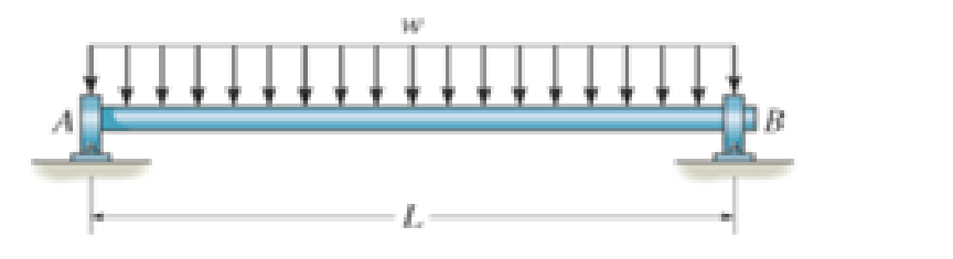
Prob. 7–54

Learn your wayIncludes step-by-step video

Chapter 7 Solutions
Engineering Mechanics: Statics Plus Modified Mastering Engineering Revision With Pearson Etext -- Access Card Package (14th Edition)
Additional Engineering Textbook Solutions
Automotive Technology: Principles, Diagnosis, And Service (6th Edition) (halderman Automotive Series)
Automotive Technology: Principles, Diagnosis, and Service (5th Edition)
Statics and Mechanics of Materials (5th Edition)
Engineering Mechanics: Statics & Dynamics (14th Edition)
Applied Fluid Mechanics (7th Edition)
Engineering Mechanics: Dynamics (14th Edition)


- Determine the shape factor of the cross section.arrow_forwardDraw the shear and moment diagrams for the shaft and determine the shear and moment throughout the shaft as a function of x for 0 … x 6 3 ft, 3 ft 6 x 6 5 ft, and 5 ft 6 x 6 6 ft. The bearings at A and B exert only vertical reactions on the shaft.arrow_forwardConstruct the shear force and bending moment diagram with the help of free body diagrams (value of Y=7)arrow_forward
- The overhang beam is made of 2014-T6 aluminum. If the 75-kg block has a speed of = 3 m>s at h = 0.75 m, determine the maximum bending stress in the beam.arrow_forwardHello, can someone help me with this problem pls. Draw the internal force (shear and moment) diagrams. Values: a = 2 m F = 150 kN q0 = 75 kN/m M0 = 450 kN-m The support at B allows movement parallel to the surface.arrow_forwardDetermine the shear force and bending moment in thecompound beam as function of the variables w and l,and draw the shear force and bending momentdiagrams.arrow_forward
- A half section of pipe rests on a frictionless horizontal surface as shown. If the half section of pipe has a mass of 9 kg and a diameter of 300 mm, determine the bending moment at point J when 0=90°.arrow_forwardDraw the shear and moment diagrams for the shaft. The bearings at A and B exert only vertical reactions on the shaft. Also, express the shear and moment in the shaft as a function of x within the region 125 mm 6 x 6 725 mm.arrow_forwardL:59)arrow_forward
- Sketch the intensity of the shear-stress distribution acting over the beam’s cross-sectional area, and determine the resultant shear force acting on the segment AB. The shear force acting at the section is V = 35 kip. Show that INA = 872.49 in4.arrow_forwardThe aluminum strut has a cross-sectional area in the form of a cross. It is subjected tothe Moment M = 8 KN.m. (i) Determine the bending stress acting at points A and B; (ii)Determine the maximum bending stress in the beam and sketch a three dimensional view of thestress distribution acting over the entire cross-sectional area.arrow_forwardThe steel tube has an elliptical cross-section of mean dimensions shown and a constant thickness of t = 0.2 in. If the allowable shear stress is tallow = 8 ksi, and the tube is to resist a torque of T = 250 lb # ft, determine the necessary dimension b. The mean area for the ellipse is Am = pb(0.5b).arrow_forward
 Elements Of ElectromagneticsMechanical EngineeringISBN:9780190698614Author:Sadiku, Matthew N. O.Publisher:Oxford University Press
 Mechanics of Materials (10th Edition)Mechanical EngineeringISBN:9780134319650Author:Russell C. HibbelerPublisher:PEARSON
 Thermodynamics: An Engineering ApproachMechanical EngineeringISBN:9781259822674Author:Yunus A. Cengel Dr., Michael A. BolesPublisher:McGraw-Hill Education
 Control Systems EngineeringMechanical EngineeringISBN:9781118170519Author:Norman S. NisePublisher:WILEY
 Mechanics of Materials (MindTap Course List)Mechanical EngineeringISBN:9781337093347Author:Barry J. Goodno, James M. GerePublisher:Cengage Learning
 Engineering Mechanics: StaticsMechanical EngineeringISBN:9781118807330Author:James L. Meriam, L. G. Kraige, J. N. BoltonPublisher:WILEY