
Concept explainers
Videos
Draw the shear force and bending moment diagrams.
Find the maximum absolute values of the shear force and bending moment.
Answer to Problem 7.50P
The maximum absolute shear force is
The maximum absolute bending moment is
Explanation of Solution
Assumption:
Apply the sign convention for calculating the equations of equilibrium as below:
- For the horizontal forces equilibrium condition, take the force acting towards right side as positive
- For the vertical forces equilibrium condition, take the upward force as positive
- For moment equilibrium condition, take the clockwise moment as negative and counter clockwise moment as positive.
Apply the following sign convention for calculating the bending moment at any section x-x while approaching from the left hand side.
- Take clockwise moment as positive and anticlockwise moment as negative
Apply the following sign convention for calculating the shear force at any section x-x while approaching from the left hand side.
- Take downward force as negative and upward force as positive.
Calculation:
Show the free-body diagram of the beam as in Figure 1.
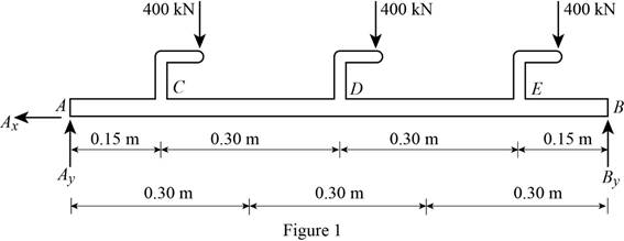
Find the vertical reaction at point B by taking moment about point A.
Find the vertical reaction at point A by resolving the vertical component of forces.
Find the horizontal reaction at point A by resolving the horizontal component of forces.
Consider a section x from left end of the beam.
Section AC
Show the free body diagram of the section as in Figure 2.
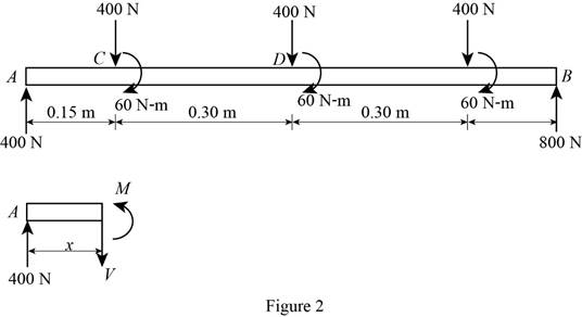
Find the shear force at the section by resolving the vertical component of forces.
Find the bending moment at the section by taking moment about the section.
When
Refer to Equation (1);
Substitute 0 for x in Equation (2).
When
Refer to Equation (1);
Substitute 0.15 m for x in Equation (2).
Section CD
Show the free body diagram of the section as in Figure 3.
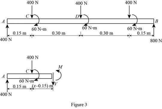
Find the shear force at the section by resolving the vertical component of forces.
Find the bending moment at the section by taking moment about the section.
When
Refer to Equation (3).
Substitute 0.15 m for x in Equation (4).
When
Refer to Equation (3).
Substitute 0.45 m for x in Equation (4).
Section DE
Show the free body diagram of the section as in Figure 4.
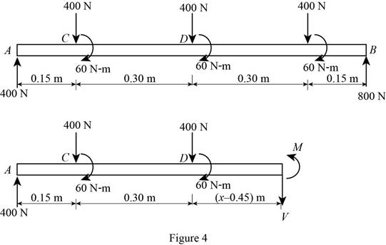
Find the shear force at the section by resolving the vertical component of forces.
Find the bending moment at the section by taking moment about the section.
When
Refer to Equation (5).
Substitute 0.45 m for x in Equation (6).
When
Refer to Equation (5).
Substitute 0.75 m for x in Equation (6).
Section EB
Show the free body diagram of the section as in Figure 5.
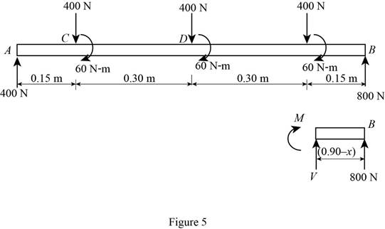
Find the shear force at the section by resolving the vertical component of forces.
Find the bending moment at the section by taking moment about the section.
When
Refer to Equation (7).
Substitute 0.75 m for x in Equation (8).
When
Refer to Equation (7).
Substitute 0.90 m for x in Equation (8).
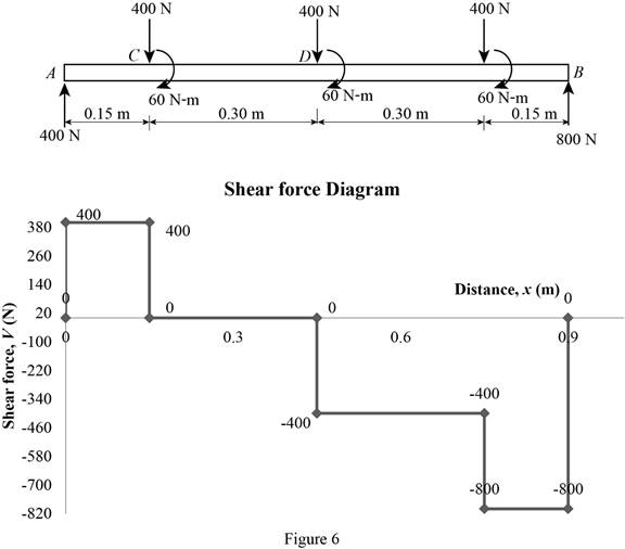
Tabulate the calculated shear force values as in Table 1.
| Distance, x (m) | Shear force, V (N) |
| 0 | 400 |
| 0.15 (Just left) | 400 |
| 0.15 (Just right) | 0 |
| 0.45 (Just left) | 0 |
| 0.45 (Just right) | –400 |
| 0.75 (Just left) | –400 |
| 0.75 (Just right) | –800 |
| 0.90 | –800 |
Plot the shear force diagram as in Figure 6.
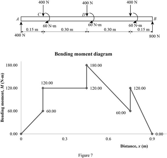
Tabulate the calculated bending moment values as in Table 2.
| Distance, x (m) | Bending moment, M (N-m) |
| 0 | 0 |
| 0.15 (Just left) | 60 |
| 0.15 (Just right) | 120 |
| 0.45 (Just left) | 120 |
| 0.45 (Just right) | 180 |
| 0.75 (Just left) | 60 |
| 0.75 (Just right) | 120 |
| 0.90 | 0 |
Plot the bending moment diagram as in Figure 7.
Refer to the Figure (6);
The maximum absolute shear force is
Refer to the Figure (7);
The maximum absolute bending moment is
Want to see more full solutions like this?
Chapter 7 Solutions
Vector Mechanics for Engineers: Statics, 11th Edition


 Elements Of ElectromagneticsMechanical EngineeringISBN:9780190698614Author:Sadiku, Matthew N. O.Publisher:Oxford University Press
 Mechanics of Materials (10th Edition)Mechanical EngineeringISBN:9780134319650Author:Russell C. HibbelerPublisher:PEARSON
 Thermodynamics: An Engineering ApproachMechanical EngineeringISBN:9781259822674Author:Yunus A. Cengel Dr., Michael A. BolesPublisher:McGraw-Hill Education
 Control Systems EngineeringMechanical EngineeringISBN:9781118170519Author:Norman S. NisePublisher:WILEY
 Mechanics of Materials (MindTap Course List)Mechanical EngineeringISBN:9781337093347Author:Barry J. Goodno, James M. GerePublisher:Cengage Learning
 Engineering Mechanics: StaticsMechanical EngineeringISBN:9781118807330Author:James L. Meriam, L. G. Kraige, J. N. BoltonPublisher:WILEY