
FUND.OF ELECTRIC CIRCUITS (LL)-W/ACCESS
6th Edition
ISBN: 9781260405927
Author: Alexander
Publisher: MCG
expand_more
expand_more
format_list_bulleted
Concept explainers
Videos
Textbook Question
Chapter 7.3, Problem 4PP
For the circuit in Fig. 7.18, find i(t) for t > 0.
Answer: 2e−2t A, t > 0.
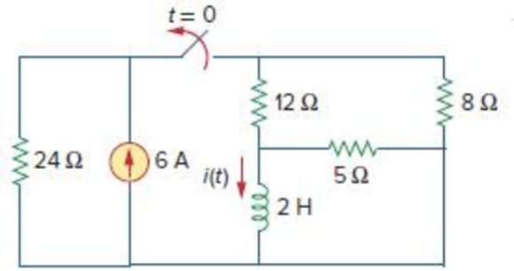
Figure 7.18
For Practice Prob. 7.4.
Expert Solution & Answer
Want to see the full answer?
Check out a sample textbook solution
Students have asked these similar questions
The switch in the circuit shown in Fig. 7.21 has been in position a for a longtime. At t=0, the switch moves from position a to position b. The switch is amake-before-break type; that is, the connection at position b is establishedbefore the connection at position a is broken, so the inductor current iscontinuous.5. Plot both i(t) and v(t) versus t.
The switch in the circuit shown in Fig. 7.6 has been closed for a long timebefore it is opened at t=0. Find 4. the percentage of the total energy stored in the 2 H inductor that isdissipated in the 10 Ω resistor.
For the following circuit obtain: (a) the response v(t) for t>0, (b) the current i(t) through the inductor for t>0.
Chapter 7 Solutions
FUND.OF ELECTRIC CIRCUITS (LL)-W/ACCESS
Ch. 7.2 - Refer to the circuit in Fig. 7.7. Let vC (0) = 60...Ch. 7.2 - If the switch in Fig. 7.10 opens at t = 0, find...Ch. 7.3 - Find i and vx in the circuit of Fig. 7.15. Let...Ch. 7.3 - For the circuit in Fig. 7.18, find i(t) for t 0....Ch. 7.3 - Determine i, io, and vo for all t in the circuit...Ch. 7.4 - Express the current pulse in Fig. 7.33 in terms of...Ch. 7.4 - Refer to Fig. 7.39. Express i(t) in terms of...Ch. 7.4 - If h t = 0, t0 4, 0t2 3t8, 2t6 0, t6 express h(t)...Ch. 7.4 - Practice Problem 7.9 Evaluate the following...Ch. 7.5 - Find v(t) for t 0 in the circuit of Fig. 7.44....
Ch. 7.5 - The switch in Fig. 7.47 is closed at t = 0. Find...Ch. 7.6 - The switch in Fig. 7.52 has been closed for a long...Ch. 7.6 - Switch S1 in Fig. 7.54 is closed at t = 0, and...Ch. 7.7 - For the op amp circuit in Fig. 7.56, find vo for t...Ch. 7.7 - Find v(t) and vo(t) in the op amp circuit of Fig....Ch. 7.7 - Obtain the step response vo(t) for the circuit in...Ch. 7.8 - For the circuit in Fig. 7.66, use Pspice to find...Ch. 7.8 - The switch in Fig. 7.71 was open for a long time...Ch. 7.9 - The RC circuit in Fig. 7.74 is designed to operate...Ch. 7.9 - The flash unit of a camera has a 2-mF capacitor...Ch. 7.9 - A relay has a resistance of 200 and an inductance...Ch. 7.9 - Prob. 22PPCh. 7 - An RC circuit has R = 2 and C = 4 F. The time...Ch. 7 - The time constant for an RL circuit with R = 2 ...Ch. 7 - A capacitor in an RC circuit with R = 2 and C = 4...Ch. 7 - An RL circuit has R = 2 and L = 4 H. The time...Ch. 7 - In the circuit of Fig. 7.79, the capacitor voltage...Ch. 7 - Figure 7.79 For Review Questions 7.5 and 7.6....Ch. 7 - For the circuit in Fig. 7.80, the inductor current...Ch. 7 - Figure 7.80 For Review Questions 7.7 and 7.8....Ch. 7 - If vs changes from 2 V to 4 V at t = 0, we may...Ch. 7 - The pulse in Fig. 7.116(a) can be expressed in...Ch. 7 - In the circuit shown in Fig. 7.81...Ch. 7 - Find the time constant for the RC circuit in Fig....Ch. 7 - Determine the time constant for the circuit in...Ch. 7 - The switch in Fig. 7.84 has been in position A for...Ch. 7 - Using Fig. 7.85, design a problem to help other...Ch. 7 - The switch in Fig. 7.86 has been closed for a long...Ch. 7 - Assuming that the switch in Fig. 7.87 has been in...Ch. 7 - For the circuit in Fig. 7.88, if...Ch. 7 - The switch in Fig. 7.89 opens at t = 0. Find vo...Ch. 7 - For the circuit in Fig. 7.90, find vo(t) for t 0....Ch. 7 - For the circuit in Fig. 7.91, find io for t 0....Ch. 7 - Using Fig. 7.92, design a problem to help other...Ch. 7 - In the circuit of Fig. 7.93,...Ch. 7 - Calculate the time constant of the circuit in Fig....Ch. 7 - Find the time constant for each of the circuits in...Ch. 7 - Determine the time constant for each of the...Ch. 7 - Consider the circuit of Fig. 7.97. Find vo(t) if...Ch. 7 - For the circuit in Fig. 7.98, determine vo(t) when...Ch. 7 - In the circuit of Fig. 7.99, find i(t) for t 0 if...Ch. 7 - For the circuit in Fig. 7.100, v = 90e50t V and i...Ch. 7 - In the circuit of Fig. 7.101, find the value of R...Ch. 7 - Find i(t) and v(t) for t 0 in the circuit of Fig....Ch. 7 - Consider the circuit in Fig. 7.103. Given that...Ch. 7 - Express the following signals in terms of...Ch. 7 - Design a problem to help other students better...Ch. 7 - Express the signals in Fig. 7.104 in terms of...Ch. 7 - Express v(t) in Fig. 7.105 in terms of step...Ch. 7 - Sketch the waveform represented by i(t) = [r(t) ...Ch. 7 - Sketch the following functions: (a) x(t) = 10etu(t...Ch. 7 - Prob. 30PCh. 7 - Evaluate the following integrals: (a)e4t2(t2)dt...Ch. 7 - Prob. 32PCh. 7 - The voltage across a 10-mH inductor is 45(t 2)mV....Ch. 7 - Evaluate the following derivatives: (a) ddtut1ut+1...Ch. 7 - Find the solution to the following differential...Ch. 7 - Solve for v in the following differential...Ch. 7 - A circuit is described by 4dvdt+v=10 (a) What is...Ch. 7 - A circuit is described by didt+3i=2ut Find i(t)...Ch. 7 - Calculate the capacitor voltage for t 0 and t 0...Ch. 7 - Find the capacitor voltage for t 0 and t 0 for...Ch. 7 - Using Fig. 7.108, design a problem to help other...Ch. 7 - (a) If the switch in Fig. 7.109 has been open for...Ch. 7 - Consider the circuit in Fig. 7.110. Find i(t) for...Ch. 7 - The switch in Fig. 7.111 has been in position a...Ch. 7 - Find vo in the circuit of Fig. 7.112 when vs =...Ch. 7 - Prob. 46PCh. 7 - Determine v(t) for t 0 in the circuit of Fig....Ch. 7 - Find v(t) and i(t) in the circuit of Fig. 7.115....Ch. 7 - If the waveform in Fig. 7.116(a) is applied to the...Ch. 7 - In the circuit of Fig. 7.117, find ix for t 0....Ch. 7 - Rather than applying the shortcut technique used...Ch. 7 - Using Fig. 7.118, design a problem to help other...Ch. 7 - Determine the inductor current i(t) for both t 0...Ch. 7 - Obtain the inductor current for both t 0 and t 0...Ch. 7 - Find v(t) for t 0 and t 0 in the circuit of Fig....Ch. 7 - Prob. 56PCh. 7 - Prob. 57PCh. 7 - Rework Prob. 7.17 if i(0) = 10 A and v(t) = 20u(t)...Ch. 7 - Determine the step response vo(t) to is = 6u(t) A...Ch. 7 - Find v(t) for t 0 in the circuit of Fig. 7.125 if...Ch. 7 - In the circuit in Fig. 7.126, is changes from 5 A...Ch. 7 - For the circuit in Fig. 7.127, calculate i(t) if...Ch. 7 - Obtain v(t) and i(t) in the circuit of Fig. 7.128....Ch. 7 - Determine the value of iL(t) and the total energy...Ch. 7 - If the input pulse in Fig. 7.130(a) is applied to...Ch. 7 - Using Fig. 7.131, design a problem to help other...Ch. 7 - If v(0) = 10 V, find vo(t) for t 0 in the op amp...Ch. 7 - Prob. 68PCh. 7 - For the op amp circuit in Fig. 7.134, find vo(t)...Ch. 7 - Determine vo for t 0 when vs = 20 mV in the op...Ch. 7 - For the op amp circuit in Fig. 7.136, suppose vs =...Ch. 7 - Find io in the op amp circuit in Fig. 7.137....Ch. 7 - For the op amp circuit of Fig. 7.138, let R1 = 10...Ch. 7 - Determine vo(t) for t 0 in the circuit of Fig....Ch. 7 - In the circuit of Fig. 7.140, find vo and io,...Ch. 7 - Repeat Prob. 7.49 using PSpice or MultiSim. If the...Ch. 7 - The switch in Fig. 7.141 opens at t = 0. Use...Ch. 7 - The switch in Fig. 7.142 moves from position a to...Ch. 7 - In the circuit of Fig. 7.143, determine io(t)....Ch. 7 - In the circuit of Fig. 7.144, find the value of io...Ch. 7 - Repeat Prob. 7.65 using PSpice or MultiSim. If the...Ch. 7 - In designing a signal-switching circuit, it was...Ch. 7 - Prob. 83PCh. 7 - A capacitor with a value of 10 mF has a leakage...Ch. 7 - A simple relaxation oscillator circuit is shown in...Ch. 7 - Figure 7.146 shows a circuit for setting the...Ch. 7 - A 120-V dc generator energizes a motor whose coil...Ch. 7 - The circuit in Fig. 7.148(a) can be designed as an...Ch. 7 - An RL circuit may be used as a differentiator if...Ch. 7 - An attenuator probe employed with oscilloscopes...Ch. 7 - The circuit in Fig. 7.150 is used by a biology...Ch. 7 - To move a spot of a cathode-ray tube across the...
Additional Engineering Textbook Solutions
Find more solutions based on key concepts
Write the nodal equations for the network of Fig. 8.137 using the general approach. Find the nodal voltages usi...
Introductory Circuit Analysis (13th Edition)
Find I0 and I1 in the circuit in Fig.P2.12.
Basic Engineering Circuit Analysis
Design an ideal inverting op-amp circuit such that the voltage gain is Av=25 . The maximum current in any resis...
Microelectronics: Circuit Analysis and Design
With respect to the circuit in Fig. 5.90, (a) employ Thévenin’s theorem to determine the equivalent network see...
Loose Leaf for Engineering Circuit Analysis Format: Loose-leaf
A constant voltage of 10V is applied to a 50H inductance, as shown in Figure P3.51 Figure P3 51 The current in ...
Electrical Engineering: Principles & Applications (7th Edition)
When travelers from the USA and Canada visit Europe, they encounter a different power distribution system. Wall...
Electric machinery fundamentals
Knowledge Booster


Learn more about
Need a deep-dive on the concept behind this application? Look no further. Learn more about this topic, electrical-engineering and related others by exploring similar questions and additional content below.Similar questions
- 11. 7.11 The switch in the circuit seen has been in position 1for a long time. At t=0, the switch moves instantaneously to position 2.Find the value of R so that 20% of the initial energy stored in the 30 mHinductor is dissipated in R in 15 μs.arrow_forward2. 7.8 The switch in the circuit has been open for a long time. The initialcharge on the capacitor is zero. At t=0 the switch is closed. Find theexpression for 2. b)v(t) for t≥0+.arrow_forwardNo energy is stored in the 100 mH inductor or the 0.4μF capacitor when theswitch in the circuit shown is closed. Find vC(t) for t≥0arrow_forward
- In the circuit below, the switch is closed at t=0 s. It is known that the voltage across the capacitor at t=0.2 s is Vc( t = 0.2 ) = 10.31 V. In this case, what will be the voltage Vc( t = 0.1 ) of the capacitor at t=0.1 s? Calculate.arrow_forwardIn the circuit below, when the switch is open for a long time, it is done at t=0. Accordingly, for t < 0, the value of i(t) is equal to which of the following?arrow_forwardIn the circuit below, the switch is closed at t=0 s. It is known that the voltage across the capacitor at t=0.2 s is Vc( t = 0.2 ) = 10.31 V. What is the initial energy of the capacitor in this case? Calculate.arrow_forward
- Consider the following circuit in which the inductor current and the capacitor voltage are equal to zero at t = 0 s. Find the value of v at t = 2 s.arrow_forward1. 7.1 The switch in the circuit shown has been closed for a long time andis opened at t=0.1. a) Calculate the initial value of i.arrow_forwardA series LR circuit has a variable inductor with theinductance L(t) is defined by intervals.Find the current i(t) if the resistance is 0.2 ohms, the voltageapplied is E(t) = 4 volts; knowing that i(0) = 0.arrow_forward
- 5) Consider the circuit shown below, in which the switch opens at t=0. Find expressions for v(t), iR(t), and iL(t) for t>0. Assume that iL(t) is zero before the switch opens.arrow_forwardThe switch in the circuit shown in the figure below has been open for a long time. It closes at t = 0s, then 1-Calculate the initial stored energy in the capacitor 2- Find the current iR(t) for t >= 0. 3- Plot the current iR(t) for t >= 0.arrow_forwardIn the circuit shown, the switch closes and is left closed for a long time. Then the switch is opened. Imediately after it is opened, what is the potential difference across the inductor L?arrow_forward
arrow_back_ios
SEE MORE QUESTIONS
arrow_forward_ios
Recommended textbooks for you
 Introductory Circuit Analysis (13th Edition)Electrical EngineeringISBN:9780133923605Author:Robert L. BoylestadPublisher:PEARSON
 Delmar's Standard Textbook Of ElectricityElectrical EngineeringISBN:9781337900348Author:Stephen L. HermanPublisher:Cengage Learning
 Programmable Logic ControllersElectrical EngineeringISBN:9780073373843Author:Frank D. PetruzellaPublisher:McGraw-Hill Education
 Fundamentals of Electric CircuitsElectrical EngineeringISBN:9780078028229Author:Charles K Alexander, Matthew SadikuPublisher:McGraw-Hill Education
 Electric Circuits. (11th Edition)Electrical EngineeringISBN:9780134746968Author:James W. Nilsson, Susan RiedelPublisher:PEARSON
 Engineering ElectromagneticsElectrical EngineeringISBN:9780078028151Author:Hayt, William H. (william Hart), Jr, BUCK, John A.Publisher:Mcgraw-hill Education,
Introductory Circuit Analysis (13th Edition)
Electrical Engineering
ISBN:9780133923605
Author:Robert L. Boylestad
Publisher:PEARSON
Delmar's Standard Textbook Of Electricity
Electrical Engineering
ISBN:9781337900348
Author:Stephen L. Herman
Publisher:Cengage Learning
Programmable Logic Controllers
Electrical Engineering
ISBN:9780073373843
Author:Frank D. Petruzella
Publisher:McGraw-Hill Education
Fundamentals of Electric Circuits
Electrical Engineering
ISBN:9780078028229
Author:Charles K Alexander, Matthew Sadiku
Publisher:McGraw-Hill Education
Electric Circuits. (11th Edition)
Electrical Engineering
ISBN:9780134746968
Author:James W. Nilsson, Susan Riedel
Publisher:PEARSON
Engineering Electromagnetics
Electrical Engineering
ISBN:9780078028151
Author:Hayt, William H. (william Hart), Jr, BUCK, John A.
Publisher:Mcgraw-hill Education,
ENA 9.2(1)(En)(Alex) Sinusoids & Phasors - Explanation with Example 9.1 ,9.2 & PP 9.2; Author: Electrical Engineering Academy;https://www.youtube.com/watch?v=vX_LLNl-ZpU;License: Standard YouTube License, CC-BY
Electrical Engineering: Ch 10 Alternating Voltages & Phasors (8 of 82) What is a Phasor?; Author: Michel van Biezen;https://www.youtube.com/watch?v=2I1tF3ixNg0;License: Standard Youtube License