
Videos
The expression for the curve made by the cable, maximum and minimum values of the tension in the cable.
Answer to Problem 7.125P
The curve represented by the cable is
Explanation of Solution
The figure 1 below shows the cable and which makes the curve due the load w.
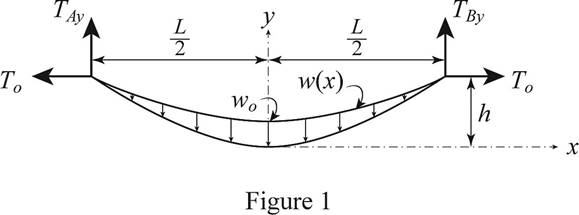
Write the expression for the load distributed.
Refer the problem 77268-7.4-7.124P and writhe the differential equation for the curve.
Write the expression for the differential equation for the curve.
Substitute
Integrate both side of the above equation and apply the condition
Integrate the above equation and apply the condition
Here C is the integration constant.
Apply the condition
Substitute
At
Substitute
The value of y at
Rewrite the above equation in terms of h.
Here
Therefore the minimum tension on the cable is
To find the maximum tension on the cable the slope of the above equation for y at
Here
Substitute
Rewrite the above equation in terms of
Write the expression to calculate the maximum tension on the cable.
Here
Substitute
Conclusion:
Thus, the curve represented by the cable is
Want to see more full solutions like this?
Chapter 7 Solutions
<LCPO> VECTOR MECH,STAT+DYNAMICS


- Calculate the forces in members AB, BH, and BG. Members BF and CG are cables which can support tension only. Forces are positive if in tension, negative if in compression. 65 6 m Answers: AB= i BH = i H BG= i 6 KN 65 B 6 m G 15 KN c 6 m 65 F E 65% kN Ξ Ξ KN KNarrow_forwardwhere fn is 55 and mn is 76arrow_forward1.Referring to the figure below, knowing that a = 20", determine the tension in (a) in cable AC. (b) in горе ВС. 1200 Ib 2. Referring to the block below, determine (a) the required value of a if the resultant of the three forces shown is to be parallel to the incline, (b) the corresponding magnitude of the resultant. 3. A transmission tower shown below, is heid by three guy wires anchored by bolts at 8, C, and D. (a) If the tension in wire AB is 525 Ib, determine the components of the force exerted by the wire on the bolt at 8. (b) A transmission tower is held by three guy wires anchored by bolts at 8, C, and D. If the tension in wire AD is 315 Ib, determine the components of the force exerted by the wire on the bolt at D. 100 t 20 25 20 60arrow_forward
- A power transmission cable consists of ten copper wires each of 1.5 mm diameter surrounding three steel wires each of 3.5 mm diameter. Determine the combined E for the compound cable and hence determine the extension of a 20 m length of the cable when it is being laid with a tension of 3 kN, For steel, E = 200GN/m2 ; for copper, E = 100GN/m2 .arrow_forward7.) A boom AB is supported in a horizontal position by a hinge at A and a cable which turns from C, over a small pulley at D. Compute the tension T in the cable and the horizontal and vertical components of the reaction at A. Neglect the size of the pulley at D. D T 8' C В A Ан K 2' 2' * 2' Av 200LB 100LBarrow_forwardThree cables are used to tie the balloon shown in Figure. Determine the magnitude of the vertical force (P) exerted by the balloon at A, knowing that the tension in cable AD is 954 N. y1 = 4.4 m y2 = 2.2 m x1 = 4.2 m x2 = 3 m z = 6 marrow_forward
- The guy wires AB and AC are attached to the top of the transmission tower. The tension in cable AB is 6.6 kN. Determine the required tension Tin cable AC such that the net effect of the two cables is a downward force at point A. Determine the magnitude R of this downward force. Assume a = 33 m, b = 39 m, c = 26 m, and d = 36 m. B Answers: T = R = i i 4.02 8.63 XXXX► kN KNarrow_forwardThe bars AB and BC of the frame shown are each of length L and connected by a pin at B in addition to the cable DE. For the loading shown, find the tension in cable DE. Given: F1= 489 KN; F2 = 978 KN and e = 60° By Cable D F1 F2 Select one: O A. TDE =472.37 KN OB. TDE =423.47 KN OC. TDE =244.50 KN OD. TDE =325.67 KN L/2 L/2 L/2 LI2arrow_forwardSituation 3. The system shown anchors a stanchion of a cable-suspended roof. If the tension in cable AB is 900 kN, what are the tensions in cables EF and EG? y G (0, 1.4, –1.2) m F E (3.4, 1, 0) m (2, 1, 0) m (1, 1.2, 0) m В (0, 1.4, 1.2) m A (2.2, 0, –1) m (2.2, 0, 1) marrow_forward
- Q.1) For the figure shown if the tension in cable AB is 15 kN, and 32.5 m long. Determine (a) the x, y, and z components of the force (BA) exerted by the cable on the support B, (b) the angles 0x, 0 y, and 0: defining the direction of that force. 28 m B 20°% 50arrow_forwardA steel tube (E = 200 GPa) with a 32-mm outer diameter and a 4-mm wall thickness is placed in a vise, which is adjusted so that its jaws just touch the ends of the tube without exerting pressure on them. The two forces shown are then applied to the tube. After these forces are applied, the vise is adjusted to decrease the distance between its jaws by 0.2 mm. It is given that P = 34 kN. NOTE: This is a multi-part question. Once an answer is submitted, you will be unable to return to this part. -80 mm +-80 mm 80 mm- B 30 kN D Determine the forces exerted by the vise on the tube at A and D. The force exerted by the vise on the tube at A is 71..5 KN→→→ The force exerted by the vise on the tube at Dis kN ←. Determine the change in length of portion BC of the tube. The change in length of portion BC of the tube is mm.arrow_forwardShow that in parabolic cables the tension acting a point depends on the x-y coordinates of this point as: T(x,y)=w0x[1+(x/2y)^2]^0.5arrow_forward
 Elements Of ElectromagneticsMechanical EngineeringISBN:9780190698614Author:Sadiku, Matthew N. O.Publisher:Oxford University Press
 Mechanics of Materials (10th Edition)Mechanical EngineeringISBN:9780134319650Author:Russell C. HibbelerPublisher:PEARSON
 Thermodynamics: An Engineering ApproachMechanical EngineeringISBN:9781259822674Author:Yunus A. Cengel Dr., Michael A. BolesPublisher:McGraw-Hill Education
 Control Systems EngineeringMechanical EngineeringISBN:9781118170519Author:Norman S. NisePublisher:WILEY
 Mechanics of Materials (MindTap Course List)Mechanical EngineeringISBN:9781337093347Author:Barry J. Goodno, James M. GerePublisher:Cengage Learning
 Engineering Mechanics: StaticsMechanical EngineeringISBN:9781118807330Author:James L. Meriam, L. G. Kraige, J. N. BoltonPublisher:WILEY