
Concept explainers
Videos
The equation for unknown flow rates or diameters for each pipe section in the pipe networks and branching pipes.
The analogy between the electric current in electric circuits and fluid flow in pipe networks.
Answer to Problem 186P
The total discharge in the branched pipe is
The analogy of network pipe is
Explanation of Solution
The following figure represents the branched pipes.
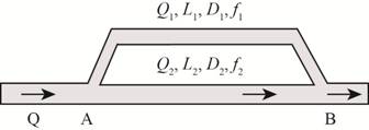
Figure-(1)
Write the expression for the area of pipe.
Here, the diameter of pipe is
Write the expression for the discharge rate in the pipe.
Here, the discharge in the pipe is
Write the expression for head loss in the pipe.
Here, the loss head is
Write the expression for total discharge in branched pipes.
Here, the total discharge in pipe is
Write the expression for head loss in the pipe 1.
Here, the velocity in pipe 1 is
Write the expression for head loss in the pipe 2.
Here, the velocity in pipe 2 is
The following figure represents the T-pipe network.

Figure (2)
Write the expressions for head loss in pipe 1.
Write the expressions for head loss in pipe 2.
Write the expressions for head loss in pipe 3.
Here, the discharge in pipe 3 is
Write the expression for loop method.
Here, the analogy of network pipe is
Calculation:
Substitute
Here, the area of pipe 1 is
Substitute
Here, the area of pipe 2 is
Substitute
Substitute
Substitute
Substitute
Substitute
The total discharge in the branched pipe is
Substitute
The analogy of network pipe is
Conclusion:
The analogy of network pipe is
The total discharge in the branched pipe is
Want to see more full solutions like this?
Chapter 8 Solutions
FLUID MECHANICS (LL) W/CONNECT


- A semi-spherical tank of radius R is completely filled with water. Now a hole of cross-sectional area Ah and discharge coefficient Cd at the bottom of the tank is fully opened and water starts to flow out. Develop an expression for the time needed to empty the tank completely.arrow_forwardThere are two fully open gate valves (KV= 2 m) and three 90° elbows (K90°= 2.2 m) on the horizontal 4 cm diameter and 100 m long line, through which water flows with a flow rate of 0.007 m3/second. Calculate the friction loss and the pressure drop due to friction in the flow in a pipe with a roughness value of (ε)0.01 cm. (Water viscosity= 10-3 kgm/s)arrow_forwardA 0.5-inch diameter water pipe is 18 m long and delivers 19 L/min. What fraction of this pipe is taken by the entrance region?[Ans. LE /L=1.7%]arrow_forward
- The height from the surface to the outlet aperture in a water filled container is 3 m. Theaperture is sharp edged with diameter 0.1 m. The discharge coefficient c d = 0.6. Find thefluid flow.arrow_forwardWhat is the entrance length in a 4-cm-diameter pipe if 0.5*10^ -4 m^ 3 / s water is flowingarrow_forwardI6 a) Determine the radial positions of a pitot tube for a 6-point traverse in a 0.3 m inner diameter pipe. Show your calculations. b) If the fluid velocity measured at the pipe center is 0.3 m/s and yields a Reynolds number based on local velocity of 4000, what is the fluid cross-sectional average velocity in the pipe? c) At what value of Re is the discharge coefficient of an orifice meter approximately independent of geometry and flow rate?arrow_forward
- Water at 25 deg C (998 kg/m 3 ) flows at 10 m 3 /s through a straight pipe of an ID of 1.38 m to 2 m-ID. Consider the level of the entrance and terminal bottom walls of the pipe equal, neglecting the effects of potential energy. In addition, the shaft work is zero. What is the Reynold's number. What kind of flow regime?arrow_forwardWater is flowing at 40L/min in a 2 cm diamter pipe, 10 m long at 20 o C. Calculate whetherthe flow is turbulent or streamline.1 m 3 = 1000 Larrow_forwardDetermine the Reynold's Number and flow regime of an bil flowing through a 450-mm diameter pipe, if the flow rate is 0.40 m³/s. Note: Hoil = 0.025 Pa's and Scoil = 0.86).arrow_forward
- A fluid at 20C flows at 850 cm3/s through an 8 cm diameter pipe. Determine the entrance length if the fluid is (a) hydrogen; (b) air; (c) gasoline; (d) water; (e) mercury; and (f) glycerin.arrow_forwardPiping system has pipes that are 130ft of 2inch inner diameter, 62ft of 5inch inner diameter, and 150ft of 3inch inner diameter. The water flows out at 20 degree C with a flow rate of 0.16ft^3/s (denisty of water is 1.936 slug/ft^3 and velocity is 1*10^-5ft^2/s) pressure drop including major losses now d o the same but only minor lossesarrow_forwardOn a single plot, show curves that show the relationship between the pressure generated by thepump as a function of flow rate of water at 20 °C through the three branches of the piping systemshown below (delta P on the y axis and flow rate on the x axis; therange of the pressure should be 0 to ~1 MPa). Pipe inner diameter: 0.03 mPipe material: copperTypical mass flow rate of interest: 0.5 kg/sIgnore minor losses of tee's at points A and B and any features of branch 3Consider minor losses of two 90° elbows in branch 2arrow_forward
 Elements Of ElectromagneticsMechanical EngineeringISBN:9780190698614Author:Sadiku, Matthew N. O.Publisher:Oxford University Press
 Mechanics of Materials (10th Edition)Mechanical EngineeringISBN:9780134319650Author:Russell C. HibbelerPublisher:PEARSON
 Thermodynamics: An Engineering ApproachMechanical EngineeringISBN:9781259822674Author:Yunus A. Cengel Dr., Michael A. BolesPublisher:McGraw-Hill Education
 Control Systems EngineeringMechanical EngineeringISBN:9781118170519Author:Norman S. NisePublisher:WILEY
 Mechanics of Materials (MindTap Course List)Mechanical EngineeringISBN:9781337093347Author:Barry J. Goodno, James M. GerePublisher:Cengage Learning
 Engineering Mechanics: StaticsMechanical EngineeringISBN:9781118807330Author:James L. Meriam, L. G. Kraige, J. N. BoltonPublisher:WILEY