
Concept explainers
Videos
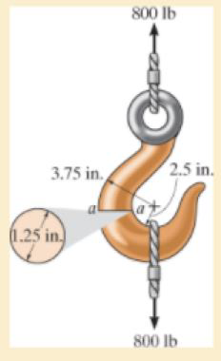
If it supports a cable loading of 800 lb, determine the maximum normal stress at section a–a and sketch the stress distribution acting over the cross section. Use the curved-beam formula to calculate the bending stress.
The maximum tensile stress
The maximum compressive stress
To sketch:
The stress distribution over the cross section.
Answer to Problem 1RP
The maximum tensile stress
The maximum compressive stress
Explanation of Solution
Given information:
The force in the cable is 800 lb.
Diameter of the circular is 1.25 in.
Calculation:
Expression to find the location of neutral
Here, R is the location of neutral axis, A is the cross sectional area of the member, r is the arbitrary position, and
Determine the radius
Here, d is the diameter of the circular cross section.
Substitute 1.25 in. for d in Equation (2).
Determine the area
Here, r is the radius of the circular cross section.
Substitute 0.625 in. for r in Equation (3).
Determine the value of
Here, c is the radius of cross section and
Find the distance measured from the center of curvature to the centroid of the cross section
Substitute 0.625 in. for c and 3.125 in. for
Substitute
Sketch the cross section of eye hook as shown in Figure 1.
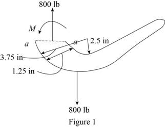
Let the moment acting at the section be M.
Express to the value of M as shown below:
Here, F is the load and R is the radius.
Determine the bending stress
Here, M is the applied moment and P is the applied load.
Substitute
Determine the maximum tensile stress
Hence, the maximum tensile stress
Determine the maximum compressive stress
Substitute
Hence, the maximum compressive stress
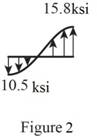
Sketch the stress distribution (tensile and compressive stress) along the cross section as shown in Figure 2.
Want to see more full solutions like this?
Chapter 8 Solutions
MECHANICS OF MATERIALS


- Determine the moment M that must be applied to the beam in order to create amaximum stress of 90 MPa. Also sketch the stress distribution acting over the cross section.arrow_forwardA member having the dimensions shown is used to resist an internal bending moment of M kNm. Determine the maximum stress in the member if the moment is applied (a) about the z axis (as shown) (b) about the y axis. Sketch the stress distribution for each case. Take: M= 90 kNm A mm A= 200 mm B= 150 mm B mm Solution: The moment of inertia of the cross-section about z and y axes are I;-4 1 - AB³ 12 (10) m* I BA = (10) m*arrow_forwardBelow Figure shows the section of an angle purlin. A bending moment of 5 kN.m is applied to the purlin in a plane at an angle of 30 deg to the vertical y axis. If the sense of the bending moment is such that both its components Mx and My produce tension in the positive xy quadrant, calculate the maximum direct stress in the purlin, stating clearly the point at which it acts. * 100 mm E 10mm 30 C D -10mm 57 MPa. 89 MPa. Non Above O 72 MPa. 125mmarrow_forward
- The wooden section of the beam is reinforced with two steel plates as shown. If the beam is subjected to a moment of M = 30 kN # m, determine the maximum bending stresses in the steel and wood. Sketch the stress distribution over the cross section. Take Ew = 10 GPa and Est = 200 GPa.arrow_forwardIf the internal moment acting on the cross-section is 800 N.m, determine the maximum tensile and compressive bending stresses acting in the beam. Sketch the stress-distribution acting on the cross-section.arrow_forward4arrow_forward
- The simply supported joist is used in the construction of a floor for a building. In order to keep the floor low with respect to the sill beams C and D, the ends of the joist are notched as shown. If the allowable shear stress is tallow = 350 psi and the allowable bending stress is s allow = 1700 psi, determine the smallest height h so that the beam will support a load of P = 600 lb. Also, will the entire joist safely support the load? Neglect the stress concentration at the notch.arrow_forwardProblem 2. Consider a rod with radius c, subject to shear force V. Clearly show the Neutral Axis on the cross-sectional area. Determine the maximum shear stress from the shear formula t=VQ/(It) and identify where these maximum shear stresses occur; write magnitude in terms of V and c. Identify the section area and section area centroid used to calculate the maximum first area moment max What is the shear stress at points A У А where t=t, max and B? What is the shear stress at the centroid? What is the shear stress at points F and E at the top and bottom? By what factor is the maximum shear stress greater than the average shear stress acting over the cross-section.arrow_forwardDetermine the moment M that should be applied to the beam in order to create a compressive stress at point D of σD = 30 MPa. Also sketch the stress distribution acting over the cross section and calculate the maximum stress in the beam. Construct the stress distribution in 2D similar to in-class examples, rather than isometrically similar to the textbook examples for clarity. Hint: The maximum stress will occur at the extreme fiber (Either top or bottom). For symmetric cross- sections, the extreme fiber for the tensile and compressive stresses will have the same magnitude. A 25 mm M D 150 mm 25 mm 25 mm B 150 mm 25 mmarrow_forward
- A small dam of a height h = 6 ft is constructed of vertical wood beams AB, as shown in the figure. The wood beams, which have a thickness I = 2.5 in., are simply supported by horizontal steel beams at A and Ä Construct a graph showing the maximum bending stress tram in the wood beams versus the depth d of the water above the lower support at B. Plot the stress0mas(psi) as the ordinate and the depth d(ft) as the abscissa. Note: The weight density y of water equals 62.4 lb/ft3.arrow_forwardQuestion 1: A member having the dimensions shown is used to resist an internal bending moment of M kNm. Determine the maximum stress in the member if the moment is applied (a) about the z axis (as shown) (b) about the y axis. Sketch the stress distribution for each case. Take: M= 98 kNm mm A= 208 mm B= 158 mm B mm Solution: The moment of inertia of the cross-section about z and y axes are 1 AB³ 12 |(10-) m* 1 ВАЗ — 12 I, |(10) m* = For the bending about z axis, c = m Mc O pax MPа Iz For the bending about y axis, c = m Mc MPа Iy max z MPa KN=M Omax Y MPa. M KN-M MPa O max Z Omax Y MPaarrow_forwardBelow Figure shows the section of an angle purlin. A bending moment of 60 5 kN.m is applied to the purlin in a plane at an angle of 30 deg to the vertical y axis. If the sense of the bending moment is such that both its components Mx and My produce tension in the positive xy quadrant, calculate the maximum direct stress in the purlin, stating clearly the point at which it acts. * 100 mm BỊ 10mm 30° C ID 10mm 57 MPa. 89 MPa. Non Above 72 MPa. 125mmarrow_forward
 Mechanics of Materials (MindTap Course List)Mechanical EngineeringISBN:9781337093347Author:Barry J. Goodno, James M. GerePublisher:Cengage Learning