
Concept explainers
Videos
(a)
Find the value of
(a)
Answer to Problem 28E
At
Explanation of Solution
Formula used:
The expression for the current flowing through the resistor is as follows.
Here,
Calculation:
The redrawn circuit diagram is given in Figure 1.
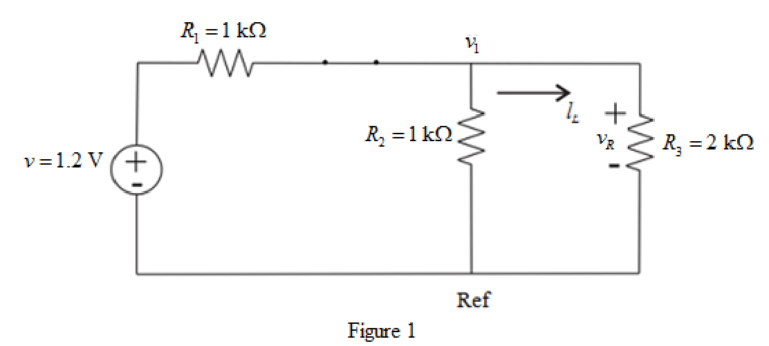
Refer to the redrawn Figure 1.
The given circuit inductor is connected for 6 years prior to being flipped open at
Apply KCL at node 1.
Here,
Substitute
Rearrange the above equation for
The voltage across
Substitute
Conclusion:
Thus, at
(b)
Find the value of
(b)
Answer to Problem 28E
At
Explanation of Solution
Calculation:
The redrawn circuit diagram is given in Figure 2.
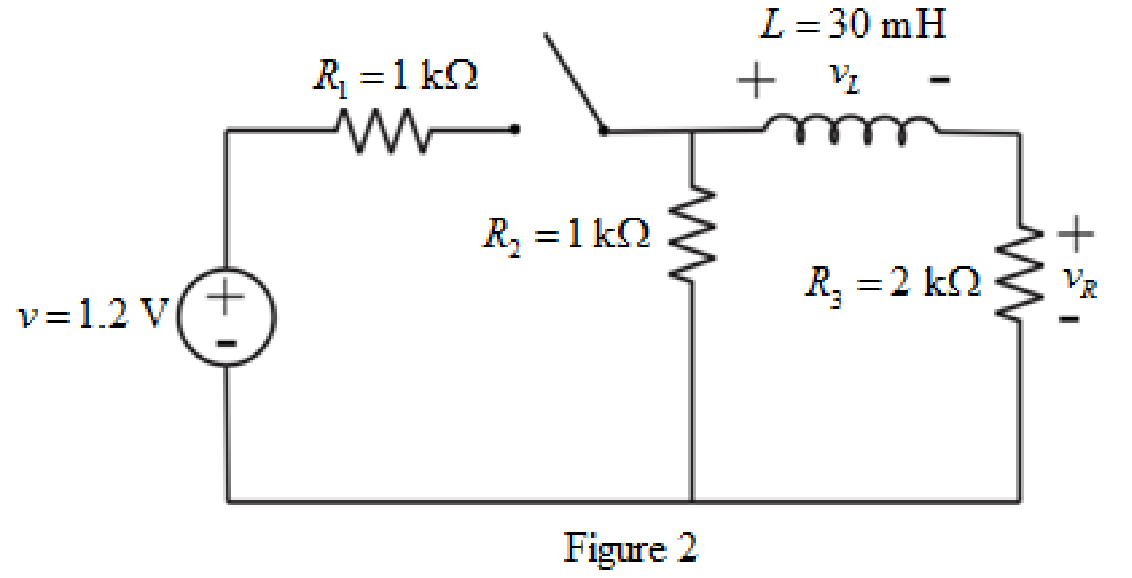
Refer to the redrawn Figure 2.
The expression for the voltage across the
Here,
Refer to the redrawn Figure 2.
The inductor does not allow sudden change in the current.
So, the current through inductor at
Apply KVL in the right side mesh.
Here,
Substitute
Rearrange for
Substitute
Conclusion:
Thus, at
(c)
Find the value of
(c)
Answer to Problem 28E
At
Explanation of Solution
Given data:
The time is
Formula used:
The expression for the equivalent resistor connected in series is as follows.
Here,
The expression for the time constant for
Here,
The expression for the current for
Here,
Calculation:
The redrawn circuit diagram is given in Figure 3.
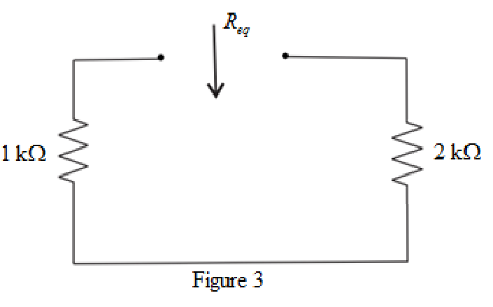
Refer to the redrawn Figure 3.
The simplified diagram is shown in Figure 4.
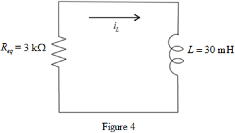
Refer to the redrawn Figure 4.
Substitute
Substitute
Substitute
Rearrange the above equation for
Substitute
Conclusion:
Thus, at
(d)
Find the value of
(d)
Answer to Problem 28E
At
Explanation of Solution
Given Data:
The time is
Calculation:
Substitute
Substitute
Rearrange the above equation for
Substitute
Conclusion:
Thus, at
Want to see more full solutions like this?
Chapter 8 Solutions
Engineering Circuit Analysis


- Calculate initial conditions for inductor current and capacitor voltage in circuit presented in Fig. 8.3. Assume: L=1H, C=0.5F, R=1Ω, e(t) = 10 2 sin(t + 45 ) V, i(t) = 2sin(t − 45 ) A.arrow_forwardThe switch in the circuit of Fig. 8.91, often called a make-before-break switch (since during switching it briefly makes contact to both parts of the circuit to ensure a smooth electrical transition), moves to position b at t = 0 only after being in position a long enough to ensure all initial transients arising from turning on the sources have long since decayed. (a) Determine the power dissipated by the 5 - resistor at t = 0−. (b) Determine the power dissipated in the 3 - resistor at t = 2 ms.arrow_forwardSuppose the input to the circuit is a damped ramp of the form Kte−100t V. Find the largest value of K such that the inductor current does not exceed the 40 mA current ratingarrow_forward
- Consider the RLC circuit shown where the initial current flowing through the circuit at time t = 0 is I_0 = 5 and the initial charge on the capacitor at time t = 0 is Q_0 = 2. The components have values of R = 100 ohms, L = 5 H, and C = 1/450,500 F. Write the differential equation for Q(t), the charge across the capacitor, assuming the voltage source V(t) = 0arrow_forwardDesign an RLC circuit with 6 uH inductance and 1 uF capacitance. Calculate the minimum value of resistance (R) for the circuit to be damped? What is the oscillation frequency of the circuit if R=1 ohms?arrow_forwardFor the circuit below with the switch closed and then opening at t=0, and R1= 3Ω, R2= 7Ω, C = 0.2H, ig = 8A, vs = 2v, calculate the initial condition. Develop the differential equation for the solution for t > 0. Calculate the current ia(t) for all times.arrow_forward
- Calculate the current in an RLC circuit with resistances R=11 ohms, L=0.1 H, and C=10^-2 F that is linked to the source V(t)= 10sin 377t. Assume that the capacitor charge and current are both zero at time t=0.arrow_forwardThe circuit elements in the circuit L=50 mH, and C=0.2 μF. The initial inductor current is−45 mA and the initial capacitor voltage is 15 V.4. The resistance is increased to 312.5 Ω. Find the expression for v(t) for t≥0.arrow_forward*The resistance, inductance, and capacitance in a parallel RLC circuit are 1900 Ω , 250 mH , and 9 nF , respectively. * Pt A. Calculate the minimum root of the characteristic equation that describes the voltage response of the circuit. Pt B. Calculate the maximum root of the characteristic equation that describes the voltage response of the circuit. Pt C.Will the response be over-, under-, or critically damped? Pt D. What value of R will yield a damped frequency of 12 krad/s? Pt E. What are the roots of the characteristic equation for the value of R found in Part D? Pt F. What value of R will result in a critically damped response?arrow_forward
- identify the following 1. If the pole’s real value is positive and is located on the right side of the S-plane. The system exponentially ____________.2. Is a continuous connection of branches from one node to another with all arrowheads in the same direction.3. Knowing the location of the pole in the S-plane determines the ______________ of the system.arrow_forward1) The circuit shown below is initially, for t < 0, with capacitor C connected to a battery (Vbat = 12 V).The key is switched at t = 0, disconnecting the battery and turning on the capacitor to the rest of the circuit.a)Calculate the circuit current in the time domain, i(t).b) In practice, after how long can the energy stored in the circuit be considered to be irrelevant (close to zero)?arrow_forward(Draw the diagram) Consider the RC circuit in which R=0.5 Ω, C=0.1 F, and E=20 V. Given that the capacitor has zero initial charge, determine the current in the circuit after 0.25 seconds.arrow_forward
 Introductory Circuit Analysis (13th Edition)Electrical EngineeringISBN:9780133923605Author:Robert L. BoylestadPublisher:PEARSON
 Delmar's Standard Textbook Of ElectricityElectrical EngineeringISBN:9781337900348Author:Stephen L. HermanPublisher:Cengage Learning
 Programmable Logic ControllersElectrical EngineeringISBN:9780073373843Author:Frank D. PetruzellaPublisher:McGraw-Hill Education
 Fundamentals of Electric CircuitsElectrical EngineeringISBN:9780078028229Author:Charles K Alexander, Matthew SadikuPublisher:McGraw-Hill Education
 Electric Circuits. (11th Edition)Electrical EngineeringISBN:9780134746968Author:James W. Nilsson, Susan RiedelPublisher:PEARSON
 Engineering ElectromagneticsElectrical EngineeringISBN:9780078028151Author:Hayt, William H. (william Hart), Jr, BUCK, John A.Publisher:Mcgraw-hill Education,