FUNDAMENTALS OF ELEC.CIRC.(LL) >CUSTOM<
6th Edition
ISBN: 9781260503876
Author: Alexander
Publisher: MCG CUSTOM
bartleby

Concept explainers

bartleby

Videos

Question
Book Icon
Chapter 8, Problem 46P
To determine

Design a problem to better understand the step response of a parallel RLC circuit.

Expert Solution & Answer
Check Mark

Explanation of Solution

Problem design:

Design a problem to understand the step response of a parallel RLC circuit if the value of resistance (R) is 2kΩ, the value of inductance (L) is 8mH, the value of capacitance (C) is 5μF, the value of voltage source (v) is 12u(t)V in the Figure 8.93 in the textbook.

Formula used:

Write an expression to calculate the neper frequency for parallel RLC circuit.

α=12RC (1)

Here,

R is the value of resistance, and

C is the value of capacitance.

Write an expression to calculate the natural frequency for parallel RLC circuit.

ω0=1LC (2)

Here,

L is the value of inductance.

The three types of responses for a series RLC circuit are,

  1.         i.            When α>ω0, the system is overdamped,
  2.       ii.            When α=ω0., the system is critically damped, and
  3.     iii.            When α<ω0, the system is under damped.

Write a general expression for the step response of a parallel RLC circuit when the response of the system is under damped.

i(t)=[Is+(A1cosωdt+A2sinωdt)eαt]A (3)

Here,

Is is the step input current,

ωd is the damped natural frequency, and

A1 and A2 are constants.

Write an expression to calculate the damped natural frequency.

ωd=ω02α2 (4)

Write an expression to calculate the value of step input.

u(t)={0t<01t>0

Calculation:

The given circuit is redrawn as shown in Figure 1.

FUNDAMENTALS OF ELEC.CIRC.(LL) >CUSTOM<, Chapter 8, Problem 46P , additional homework tip  1

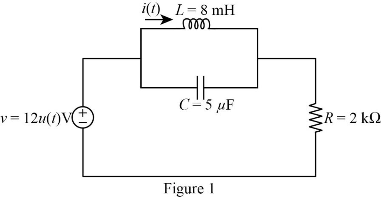
For a DC circuit at steady state condition when time t=0 the capacitor acts like open circuit and the inductor acts like short circuit. The value of step input for t<0 is zero.

Since the value of step input is zero, the voltage source becomes zero. If the value of voltage source is zero, it acts as a short circuit. Now, the Figure 1 is reduced as shown in Figure 2.

FUNDAMENTALS OF ELEC.CIRC.(LL) >CUSTOM<, Chapter 8, Problem 46P , additional homework tip  2

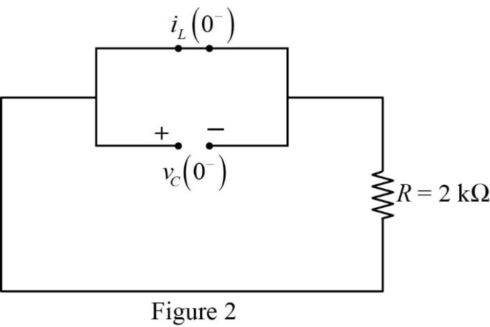
Refer to Figure 2, there is no current and voltage through the circuit. Therefore, the current flows through inductor and voltage across the capacitor is zero.

iL(0)=0A

vC(0)=0V

The current through inductor and voltage across the capacitor is always continuous so that,

i(0)=iL(0)=iL(0+)=0A

v(0)=vC(0)=vC(0+)=0V

For t>0, the value of step input is 1. Therefore, the voltage source becomes,

v=12(1)V{u(t)=1fort>0}=12V

Now, the Figure 1 is reduced as shown in Figure 3.

FUNDAMENTALS OF ELEC.CIRC.(LL) >CUSTOM<, Chapter 8, Problem 46P , additional homework tip  3

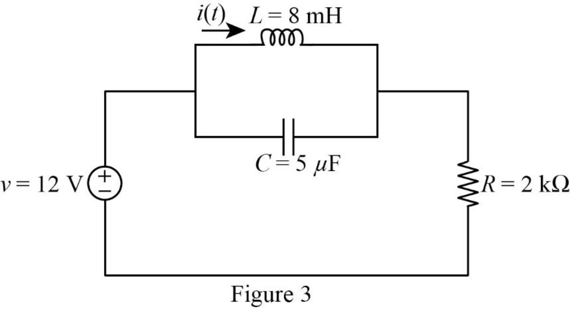
The Figure 3 can also be drawn as shown in Figure 4.

FUNDAMENTALS OF ELEC.CIRC.(LL) >CUSTOM<, Chapter 8, Problem 46P , additional homework tip  4

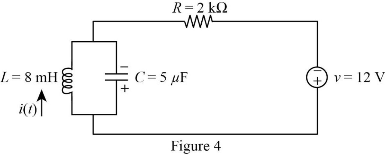
Use source transformation to convert the voltage source (v) into current source (i1).

i1=vR (5)

Substitute 12V for v, and 2kΩ for R in equation (5) to find i1.

i1=12V2kΩ=12V2×103Ω{1k=103}=6×10³A=6mA{1m=103}

Now, the Figure 4 is reduced as shown in Figure 5.

FUNDAMENTALS OF ELEC.CIRC.(LL) >CUSTOM<, Chapter 8, Problem 46P , additional homework tip  5

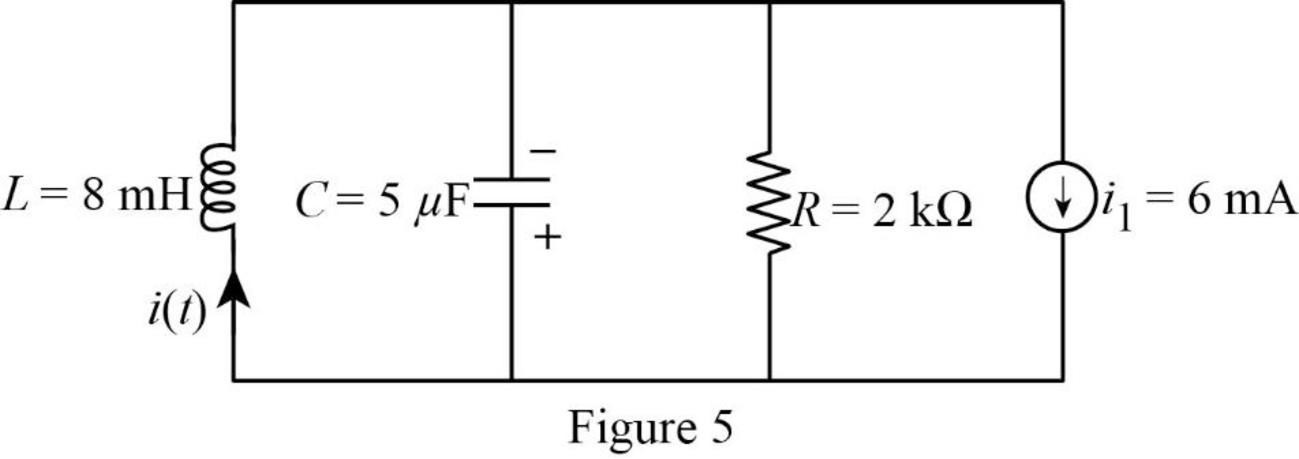
Refer to Figure 5, the circuit shows the step response of a parallel RLC circuit.

Substitute 2kΩ for R, and 5μF for C in equation (1) to find α.

α=12(2kΩ)(5μF)=12(2×10³Ω)(5×10⁶F){1k=103,1μ=106}=12(2×10³Ω)(5×10⁶sΩ){1F=1s1Ω}=50Nps

Substitute 8mH for L, and 5μF for C in equation (2) to find ω0.

ω0=1(8mH)(5μF)=1(8×10³H)(5×10⁶F){1k=103,1μ=106}=1(8×10³s2F)(5×10⁶F){1H=1s21F}=5000rads

Comparing the value of neper and natural frequency, the value of neper frequency is greater than the natural frequency α<ω0. Therefore, the system is under damped.

Substitute 50 for α, and 5000 for ω0 in equation (4) to find ωd.

ωd=(5000)2(50)2=5000

Substitute 50 for α, and 5000 for ωd in equation (3) to find i(t).

i(t)=[Is+(A1cos(5000t)+A2sin(5000t))e50t]A (6)

For a time t, the circuit again reaches steady state, the capacitor acts like open circuit and the inductor acts like short circuit.

Now, the reduced circuit of Figure 5 is shown in Figure 6.

FUNDAMENTALS OF ELEC.CIRC.(LL) >CUSTOM<, Chapter 8, Problem 46P , additional homework tip  6

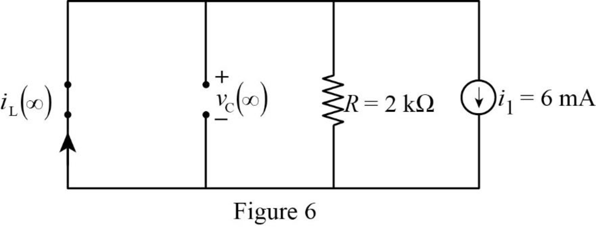
Refer to Figure 6, the short circuited inductor and resistor are connected in parallel. Since the full current flows through the short circuited inductor, the resistor is also shorted. Now, the reduced diagram of Figure 6 is shown in Figure 7.

FUNDAMENTALS OF ELEC.CIRC.(LL) >CUSTOM<, Chapter 8, Problem 46P , additional homework tip  7

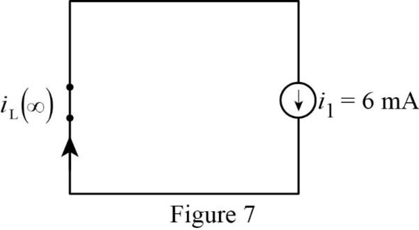
Refer to Figure 7, the current flows through the inductor is same as the current source (i1).

iL()=6mA

For a step input,

Is=iL()=i() (7)

Substitute 6mA for iL() in equation (7) to find Is.

Is=6mA

Substitute 6mA for Is in equation (6) to find i(t).

i(t)=[6mA+(A1cos(5000t)+A2sin(5000t))e50tA]

i(t)=[6mA+A1e50tcos(5000t)A+A2e50tsin(5000t)A] (8)

Substitute 0 for t in equation (8) to find i(0).

i(0)=[6mA+A1e50(0)cos(5000(0))A+A2e50(0)sin(5000(0))A]=[(6×10³)A+A1(1)cos(0)A+A2(1)sin(0)A]{e0=1,1m=103}=[(6×10³)A+A1(1)(1)A+A2(1)(0)A]{cos0°=1,sin0°=0}i(0)=[(6×10³)+A1]A (9)

Substitute 0A for i(0) in equation (9) to find A1.

0A=[(6×10³)+A1]A(6×10³)+A1=0

Simplify the above equation to find A1.

A1=6×10³

Differentiate equation (8) with respect to t to find di(t)dt.

di(t)dt=[0+A1e50t(50)cos(5000t)+A1e50t(sin(5000t))(5000)+A2e50t(50)sin(5000t)+A2e50t(cos(5000t))(5000)]As

di(t)dt=[50A1e50tcos(5000t)5000A1e50tsin(5000t)50A2e50tsin(5000t)+5000A2e50tcos(5000t)]As (10)

Substitute 0 for t in equation (10) to find di(0)dt.

di(0)dt=[50A1e50(0)cos(5000(0))5000A1e50(0)sin(5000(0))50A2e50(0)sin(5000(0))+5000A2e50(0)cos(5000(0))]As=[50A1(1)cos(0)5000A1(1)sin(0)50A2(1)sin(0)+5000A2(1)cos(0)]As{e0=1}=[50A1(1)(1)5000A1(1)(0)50A2(1)(0)+5000A2(1)(1)]As{cos0°=1,sin0°=0}

di(0)dt=[50A1+5000A2]As (11)

For the parallel RLC circuit, the voltage across the resistor, inductor and capacitor are same.

v(t)=vR(t)=vL(t)=vC(t)

Write an expression to calculate the voltage across inductor.

vL(t)=Ldi(t)dt (12)

Substitute v(t) for vL(t) in equation (12) to find v(t).

v(t)=Ldi(t)dt (13)

Rearrange equation (13) to find di(t)dt.

di(t)dt=v(t)L (14)

Substitute 0 for t in equation (14) to find di(0)dt.

di(0)dt=v(0)L (15)

Substitute 0V for v(0), and 8mH for L in equation (15) to find di(0)dt.

di(0)dt=0V8mH=0V8×103H{1m=103}=0V8×103(VsA){1H=1V1s1A}=0As

Substitute 0As for di(0)dt in equation (11) to find A2.

0As=[50A1+5000A2]As50A1+5000A2=05000A2=50A1

Simplify the above equation to find A2.

A2=50A15000 (16)

Substitute 6×10³ for A1 in equation (16) to find A2.

A2=50(6×10³)5000=0.06×10³

Substitute 6×10³ for A1, and 0.06×10³ for A2 in equation (8) to find i(t).

i(t)=[6mA+(6×10³)e50tcos(5000t)A+(0.06×10³)e50tsin(5000t)A]=[6×10³+(6×10³)e50tcos(5000t)+(0.06×10³)e50tsin(5000t)]A{1m=103}=[66e50tcos(5000t)0.06e50tsin(5000t)]×103A=[6(6cos(5000t)+0.06sin(5000t))e50t]u(t)mA{1m=103,u(t)=1fort>0}

Therefore, the expression of current i(t) for t>0 is [6(6cos(5000t)+0.06sin(5000t))e50t]u(t)mA.

Conclusion:

Thus, thus a problem to make the better understand of a step response of a parallel RLC circuit is designed.

Want to see more full solutions like this?

Subscribe now to access step-by-step solutions to millions of textbook problems written by subject matter experts!
Students have asked these similar questions
Consider the following circuit in which the inductor current and the capacitor voltage are equal to zero at t = 0 s.  Find the value of v at t = 2 s.
Select such state variables for the above RLC circuit so that the state equations of the system can be written in the form x = Ax +Bu , y=Cx+Du. Show it.
The voltage applied to a series RLC circuit is v = 200 sin 200t volts and the resulting current is i = 5 sin (200t + 40degree) amp. The capacitor in series has a value of 30 microfarad. Find the inductance of the circuit in Henry.

Chapter 8 Solutions

FUNDAMENTALS OF ELEC.CIRC.(LL) >CUSTOM<

Ch. 8.8 - In the op amp circuit shown in Fig. 8.34, vs =...Ch. 8.9 - Find i(t) using PSpice for 0 t 4 s if the pulse...Ch. 8.9 - Refer to the circuit in Fig. 8.21 (see Practice...Ch. 8.10 - Draw the dual circuit of the one in Fig. 8.46.Ch. 8.10 - For the circuit in Fig. 8.50, obtain the dual...Ch. 8.11 - In Fig. 8.52, find the capacitor voltage vC for t ...Ch. 8.11 - The output of a D/A converter is shown in Fig....Ch. 8 - For the circuit in Fig. 8.58, the capacitor...Ch. 8 - For Review Questions 8.1 and 8.2. 8.2For the...Ch. 8 - When a step input is applied to a second-order...Ch. 8 - If the roots of the characteristic equation of an...Ch. 8 - In a series RLC circuit, setting R = 0 will...Ch. 8 - Prob. 6RQCh. 8 - Refer to the series RLC circuit in Fig. 8.59. What...Ch. 8 - Consider the parallel RLC circuit in Fig. 8.60....Ch. 8 - Match the circuits in Fig. 8.61 with the following...Ch. 8 - Prob. 10RQCh. 8 - For the circuit in Fig. 8.62, find: (a)i(0+) and...Ch. 8 - Using Fig. 8.63, design a problem to help other...Ch. 8 - Refer to the circuit shown in Fig. 8.64....Ch. 8 - In the circuit of Fig. 8.65, find: (a) v(0+) and...Ch. 8 - Refer to the circuit in Fig. 8.66. Determine: (a)...Ch. 8 - In the circuit of Fig. 8.67, find: (a) vR(0+) and...Ch. 8 - A series RLC circuit has R = 20 k, L = 0.2 mH, and...Ch. 8 - Design a problem to help other students better...Ch. 8 - The current in an RLC circuit is described by...Ch. 8 - The differential equation that describes the...Ch. 8 - Prob. 11PCh. 8 - If R = 50 , L = 1.5 H, what value of C will make...Ch. 8 - For the circuit in Fig. 8.68, calculate the value...Ch. 8 - The switch in Fig. 8.69 moves from position A to...Ch. 8 - The responses of a series RLC circuit are...Ch. 8 - Find i(t) for t 0 in the circuit of Fig. 8.70....Ch. 8 - In the circuit of Fig. 8.71, the switch...Ch. 8 - Find the voltage across the capacitor as a...Ch. 8 - Obtain v(t) for t 0 in the circuit of Fig. 8.73....Ch. 8 - The switch in the circuit of Fig. 8.74 has been...Ch. 8 - Calculate v(t) for t 0 in the circuit of Fig....Ch. 8 - Assuming R = 2 k, design a parallel RLC circuit...Ch. 8 - For the network in Fig. 8.76, what value of C is...Ch. 8 - The switch in Fig. 8.77 moves from position A to...Ch. 8 - Using Fig. 8.78, design a problem to help other...Ch. 8 - The step response of an RLC circuit is given by...Ch. 8 - Prob. 27PCh. 8 - A series RLC circuit is described by...Ch. 8 - Solve the following differential equations subject...Ch. 8 - Prob. 30PCh. 8 - Consider the circuit in Fig. 8.79. Find vL(0+) and...Ch. 8 - For the circuit in Fig. 8.80, find v(t) for t 0.Ch. 8 - Find v(t) for t 0 in the circuit of Fig. 8.81.Ch. 8 - Calculate i(t) for t 0 in the circuit of Fig....Ch. 8 - Using Fig. 8.83, design a problem to help other...Ch. 8 - Obtain v(t) and i(t) for t 0 in the circuit of...Ch. 8 - For the network in Fig. 8.85, solve for i(t) for t...Ch. 8 - Refer to the circuit in Fig. 8.86. Calculate i(t)...Ch. 8 - Determine v(t) for t 0 in the circuit of Fig....Ch. 8 - The switch in the circuit of Fig. 8.88 is moved...Ch. 8 - For the network in Fig. 8.89, find i(t) for t 0....Ch. 8 - Given the network in Fig. 8.90, find v(t) for t ...Ch. 8 - The switch in Fig. 8.91 is opened at t = 0 after...Ch. 8 - A series RLC circuit has the following parameters:...Ch. 8 - In the circuit of Fig. 8.92, find v(t) and i(t)...Ch. 8 - Prob. 46PCh. 8 - Find the output voltage vo(t) in the circuit of...Ch. 8 - Given the circuit in Fig. 8.95, find i(t) and v(t)...Ch. 8 - Determine i(t) for t 0 in the circuit of Fig....Ch. 8 - For the circuit in Fig. 8.97, find i(t) for t 0....Ch. 8 - Find v(t) for t 0 in the circuit of Fig. 8.98....Ch. 8 - The step response of a parallel RLC circuit is...Ch. 8 - After being open for a day, the switch in the...Ch. 8 - Using Fig. 8.100, design a problem to help other...Ch. 8 - For the circuit in Fig. 8.101, find v(t) for t 0....Ch. 8 - In the circuit of Fig. 8.102, find i(t) for t 0....Ch. 8 - Given the circuit shown in Fig. 8.103, determine...Ch. 8 - In the circuit of Fig. 8.104, the switch has been...Ch. 8 - The switch in Fig. 8.105 has been in position 1...Ch. 8 - Obtain i1 and i2 for t 0 in the circuit of Fig....Ch. 8 - For the circuit in Prob. 8.5, find i and v for t ...Ch. 8 - Find the response vR(t) for t 0 in the circuit of...Ch. 8 - For the op amp circuit in Fig. 8.108, find the...Ch. 8 - Using Fig. 8.109, design a problem to help other...Ch. 8 - Determine the differential equation for the op amp...Ch. 8 - Obtain the differential equations for vo(t) in the...Ch. 8 - In the op amp circuit of Fig. 8.112, determine...Ch. 8 - For the step function vs = u(t), use PSpice or...Ch. 8 - Given the source-free circuit in Fig. 8.114, use...Ch. 8 - For the circuit in Fig. 8.115, use PSpice or...Ch. 8 - Obtain v(t) for 0 t 4 s in the circuit of Fig....Ch. 8 - The switch in Fig. 8.117 has been in position 1...Ch. 8 - Design a problem, to be solved using PSpice or...Ch. 8 - Draw the dual of the circuit shown in Fig. 8.118.Ch. 8 - Obtain the dual of the circuit in Fig. 8.119.Ch. 8 - Find the dual of the circuii in Fig. 8.120.Ch. 8 - Draw the dual of the circuit in Fig. 8.121.Ch. 8 - An automobile airbag igniter is modeled by the...Ch. 8 - A load is modeled as a 100-mH inductor in parallel...Ch. 8 - A mechanical system is modeled by a series RLC...Ch. 8 - An oscillogram can be adequately modeled by a...Ch. 8 - The circuit in Fig. 8.123 is the electrical analog...Ch. 8 - Figure 8.124 shows a typical tunnel-diode...
Knowledge Booster
Background pattern image
Electrical Engineering
Learn more about
Need a deep-dive on the concept behind this application? Look no further. Learn more about this topic, electrical-engineering and related others by exploring similar questions and additional content below.
Similar questions
SEE MORE QUESTIONS
Recommended textbooks for you
Text book image
Introductory Circuit Analysis (13th Edition)
Electrical Engineering
ISBN:9780133923605
Author:Robert L. Boylestad
Publisher:PEARSON
Text book image
Delmar's Standard Textbook Of Electricity
Electrical Engineering
ISBN:9781337900348
Author:Stephen L. Herman
Publisher:Cengage Learning
Text book image
Programmable Logic Controllers
Electrical Engineering
ISBN:9780073373843
Author:Frank D. Petruzella
Publisher:McGraw-Hill Education
Text book image
Fundamentals of Electric Circuits
Electrical Engineering
ISBN:9780078028229
Author:Charles K Alexander, Matthew Sadiku
Publisher:McGraw-Hill Education
Text book image
Electric Circuits. (11th Edition)
Electrical Engineering
ISBN:9780134746968
Author:James W. Nilsson, Susan Riedel
Publisher:PEARSON
Text book image
Engineering Electromagnetics
Electrical Engineering
ISBN:9780078028151
Author:Hayt, William H. (william Hart), Jr, BUCK, John A.
Publisher:Mcgraw-hill Education,
ENA 9.2(1)(En)(Alex) Sinusoids & Phasors - Explanation with Example 9.1 ,9.2 & PP 9.2; Author: Electrical Engineering Academy;https://www.youtube.com/watch?v=vX_LLNl-ZpU;License: Standard YouTube License, CC-BY
Electrical Engineering: Ch 10 Alternating Voltages & Phasors (8 of 82) What is a Phasor?; Author: Michel van Biezen;https://www.youtube.com/watch?v=2I1tF3ixNg0;License: Standard Youtube License