
Concept explainers
Videos
Refer to Figure 8-21. Assume that the resistors have the following values:
Assume that an ohmmeter connected across the entire circuit indicates a value of 245
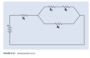
FIGURE 8-21 Series-parallel circuit.

Trending nowThis is a popular solution!

Chapter 8 Solutions
DELMAR'S STANDARD TEXT OF ELECTRICITY


- Refer to the circuit shown in Figure 6-22. The circuit has an applied voltage of 24 V and the resistors have values as follows: R1=1kR2=300R3=750R4=1k An ammeter and a voltmeter indicate the following values: IT=42.5mAI1=24mAE1=24VI2=18.5mAE2=5.5VI3=0AE3=18.5VI4=18.5mAE4=18.5V What is the most likely problem with this circuit? FIGURE 8-22 Determine resistor values using the color code and find all missing electrical values.arrow_forwardMaximum power is delivered to the load when load resistance is equal to open circuit resistance current O Ground resistance Rtharrow_forwardCalculate the total resistance ZT using the resistance value Frequency is 400hz Vs peak 5Varrow_forward
- Figure 5 shows a current series feedback amplifier. The sampled current signal is the output current, I, flowing in resistor, Rg, where it develops a feedback signal voltage, V across the resistor, Rg. Determine: a) the feedback gain, B = I. 1. Io the gain without feedback, A = Vs b) A c) the gain with feedback, Af 1+BAarrow_forwardA current source with parallel resistance can be converted into a voltage source with ---- resistance. series parallel series or parallel O noarrow_forward8. (5) 1 kOhm resistors are in series with (7) 3.3 kOhm resistors. The total resistance is most near: 12 kOhm 10.3 kOhm 22.3 kOhm O 28 kOhmarrow_forward
- Calculate voltage across the load resistor and draw the output voltage waveform in the following circuitarrow_forwardCircuits 1 HW 4 Q7 The figure is right below the question there isn’t anything else that goes with itarrow_forwardIf two resistors with resistance 6.0 Q and 8.0 Q are connected in series with 12.0 volt source, then find the overall current in circuit. A 0.86 A B 0.56A C 0.22A D 1.24Aarrow_forward
- For the following circuits, solve for the values as indicated. Round your answers to the nearest hundredth Solve for the Total Resistance. Rt 2. Use the figure to solve for the following total ww RO M 90 w Marrow_forwardUsing Nodal Analysis Redraw the circuit and determine the values of all voltages across each of the resistors. 60 0 ww 40 a 30 0 10 V 20 V 10 0 20 0arrow_forwardWhat are the expected voltages at points C and D of this circuit? 10 0 10 0 12 V 12 V O 12 V and 12 V 2V and 0 V 10 V and 2 V 6 V and 0 Varrow_forward
 Delmar's Standard Textbook Of ElectricityElectrical EngineeringISBN:9781337900348Author:Stephen L. HermanPublisher:Cengage Learning
 Electricity for Refrigeration, Heating, and Air C...Mechanical EngineeringISBN:9781337399128Author:Russell E. SmithPublisher:Cengage Learning