Connect 1-Semester Access Card for Mechanics of Materials
7th Edition
ISBN: 9780077625207
Author: Ferdinand P. Beer, E. Russell Johnston Jr., John T. DeWolf, David Mazurek
Publisher: McGraw-Hill Education
expand_more
expand_more
format_list_bulleted
Videos
Textbook Question
Chapter 8, Problem 67RP
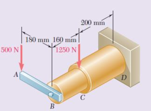
Knowing that rods BC and CD are of diameter 24 mm and 36 mm, respectively, determine the maximum shearing stress in each rod. Neglect the effect of fillets and of stress concentrations.
Fig. P8.66 and P8.67
Expert Solution & Answer
Want to see the full answer?
Check out a sample textbook solution
Students have asked these similar questions
Two wooden members are joined by plywood splice plates that are fully glued on the contact surfaces. Knowing that the clearance between the ends of the members is 6 mm and that the ultimate shearing stress in the glued joint is 2.5 MPa, determine the length L for which the factor of safety is 2.75 for the loading shown. Take P = 13 kN.
A torque of magnitude T=12 kN·m is applied to the end of a tank containing compressed air under a pressure of 8 MPa. Knowing that the tank has a 180-mm inner diameter and a 12-mm wall thickness, determine the maximum normal stress and the maximum in-plane shearing stress in the tank.
The driveshaft of an automobile is being designed to transmit 238 hp at 3790 rpm. Determine the minimum diameter d required for a solid steel shaft if the allowable shear stress in the shaft is not to exceed 5700 psi.
Chapter 8 Solutions
Connect 1-Semester Access Card for Mechanics of Materials
Ch. 8.2 - A W10 = 39 rolled-steel beam supports a load P as...Ch. 8.2 - Solve Prob. 8.1, assuming that P = 22.5 kips and a...Ch. 8.2 - An overhanging W920 449 rolled-steel beam...Ch. 8.2 - Solve Prob. 8.3, assuming that P = 850 kN and a =...Ch. 8.2 - 8.5 and 8.6 (a) Knowing that all = 160 MPa and all...Ch. 8.2 - 8.5 and 8.6 (a) Knowing that all = 160 MPa and all...Ch. 8.2 - 8.7 and 8.8 (a) Knowing that all = 24 ksi and all...Ch. 8.2 - 8.7 and 8.8 (a) Knowing that all = 24 ksi and all...Ch. 8.2 - 8.9 through 8.14 Each of the following problems...Ch. 8.2 - 8.9 through 8.14 Each of the following problems...
Ch. 8.2 - 8.9 through 8.14 Each of the following problems...Ch. 8.2 - Prob. 12PCh. 8.2 - 8.9 through 8.14 Each of the following problems...Ch. 8.2 - 8.9 through 8.14 Each of the following problems...Ch. 8.2 - Determine the smallest allowable diameter of the...Ch. 8.2 - Determine the smallest allowable diameter of the...Ch. 8.2 - Using the notation of Sec. 8.2 and neglecting the...Ch. 8.2 - The 4-kN force is parallel to the x axis, and the...Ch. 8.2 - The vertical force P1 and the horizontal force P2...Ch. 8.2 - The two 500-lb forces are vertical and the force P...Ch. 8.2 - Prob. 21PCh. 8.2 - Prob. 22PCh. 8.2 - The solid shaft AB rotates at 600 rpm and...Ch. 8.2 - The solid shaft AB rotates at 600 rpm and...Ch. 8.2 - The solid shafts ABC and DEF and the gears shown...Ch. 8.2 - Prob. 26PCh. 8.2 - Prob. 27PCh. 8.2 - Prob. 28PCh. 8.2 - The solid shaft AE rotates at 600 rpm and...Ch. 8.2 - The solid shaft AE rotates at 600 rpm and...Ch. 8.3 - Two 1.2-kip forces are applied to an L-shaped...Ch. 8.3 - Two 1.2-kip forces are applied to an L-shaped...Ch. 8.3 - The cantilever beam AB has a rectangular cross...Ch. 8.3 - 8.34 through 8.36 Member AB has a uniform...Ch. 8.3 - 8.34 through 8.36 Member AB has a uniform...Ch. 8.3 - 8.34 through 8.36 Member AB has a uniform...Ch. 8.3 - Prob. 37PCh. 8.3 - Two forces are applied to the pipe AB as shown....Ch. 8.3 - Several forces are applied to the pipe assembly...Ch. 8.3 - The steel pile AB has a 100-mm outer diameter and...Ch. 8.3 - Three forces are applied to a 4-in.-diameter plate...Ch. 8.3 - The steel pipe AB has a 72-mm outer diameter and a...Ch. 8.3 - A 13-kN force is applied as shown to the...Ch. 8.3 - A vertical force P of magnitude 60 lb is applied...Ch. 8.3 - Three forces are applied to the bar shown....Ch. 8.3 - Prob. 46PCh. 8.3 - Three forces are applied to the bar shown....Ch. 8.3 - Three forces are applied to the bar shown....Ch. 8.3 - Two forces are applied to the small post BD as...Ch. 8.3 - Two forces are applied to the small post BD as...Ch. 8.3 - Three forces are applied to the machine component...Ch. 8.3 - Prob. 52PCh. 8.3 - Three steel plates, each 13 mm thick, are welded...Ch. 8.3 - Three steel plates, each 13 mm thick, are welded...Ch. 8.3 - Two forces P1 and P2 are applied as shown in...Ch. 8.3 - Two forces P1 and P2 are applied as shown in...Ch. 8.3 - Prob. 57PCh. 8.3 - Four forces are applied to a W8 28 rolled-steel...Ch. 8.3 - A force P is applied to a cantilever beam by means...Ch. 8.3 - Prob. 60PCh. 8.3 - A 5-kN force P is applied to a wire that is...Ch. 8.3 - Knowing that the structural tube shown has a...Ch. 8.3 - The structural tube shown has a uniform wall...Ch. 8.3 - The structural tube shown has a uniform wall...Ch. 8 - (a) Knowing that all = 24 ksi and all = 14.5 ksi,...Ch. 8 - Neglecting the effect of fillets and of stress...Ch. 8 - Knowing that rods BC and CD are of diameter 24 mm...Ch. 8 - The solid shaft AB rotates at 450 rpm and...Ch. 8 - A 6-kip force is applied to the machine element AB...Ch. 8 - A thin strap is wrapped around a solid rod of...Ch. 8 - A close-coiled spring is made of a circular wire...Ch. 8 - Forces are applied at points A and B of the solid...Ch. 8 - Knowing that the bracket AB has a uniform...Ch. 8 - For the post and loading shown, determine the...Ch. 8 - Knowing that the structural tube shown has a...Ch. 8 - The cantilever beam AB will be installed so that...
Knowledge Booster


Learn more about
Need a deep-dive on the concept behind this application? Look no further. Learn more about this topic, mechanical-engineering and related others by exploring similar questions and additional content below.Similar questions
- The preliminary design of a motor-to-generator connection calls for the use of a large hollow shaft with inner and outer diameters of 4 in. and 6 in., respectively. Knowing that the allowable shearing stress is 12 ksi, determine the maximum torque that can be transmitted by (a) the shaft as designed, (b) a solid shaft of the same weight, and (c) a hollow shaft of the same weight and an 8-in. outer diameter.arrow_forwardA 10 mm diameter specimen of hardened tool steel was tested in double shear and failed under a load of 106.8 kN. If a machine-tool component of square cross-section 12 mm x 12 mm is made from the same material, determine the maximum shear load in single shear allowed if the factor of safety is to be 4.arrow_forwardA spherical gas container made of steel has a 20-ft outer diameter and a wall thickness of 7/16 in. Knowing that the internal pressure is 75 psi, determine the maximum normal stress and the maximum shearing stress in the container.arrow_forward
- The wooden members A and B are to be joined by plywood splice plates that will be fully glued on the surfaces in contact. As part of the design of the joint, and knowing that the clearance between the ends of the members is to be 8 mm, determine the smallest allowable length L if the average shearing stress in the glue is not to exceed 800 kPa.arrow_forwardPart of a steel tube, 30mm external diameter and 6mm thick, is to be enlarged to form a compound tube of external diameter 40mm. Determine: The metal thickness of the enlarged section if the maximum shear stress is to be the same in both sections, when the compound tube is subjected to a torquearrow_forwardThe design specifications of a 1.2-m-long solid transmission shaft require that the angle of twist of the shaft not exceed 4° when a torque of 750 N·m is applied. Determine the required diameter of the shaft, knowing that the shaft is made of a steel with an allowable shearing stress of 90 MPa and a modulus of rigidity of 77.2 GPa.arrow_forward
- Knowing that a given vertical shear V causes a maximum shearing stress of 50 MPa in a thin-walled member having the cross section shown, determine the corresponding shearing stress at (a) point a, (b) point b, (c) point c.arrow_forwardTwo wooden planks, each 7/8 in thick and 6in wide, are joined by the glued mortise joint shown. Knowing that the wood used shears off along its grain when the average shearing stress reaches 120psi, determine the smallest allowable length d of the cuts if the joint is to withstand an axial load of magnitude P=1200-lb. Note: Seven surfaces carry the load, P=1200-lbarrow_forwardA 88-N·m torque is applied to a hollow shaft having the cross section shown. Neglecting the effect of stress concentrations, determine the shearing stress at points a and b. The shearing stress at point a is MPa. The shearing stress at point b is MPa.arrow_forward
- A flange coupling connects two 2 inch diameter shaft. The flanges are fitted by 6 bolts on a 7 “ bolt circle. If the shaft rotates at 300 rpm and transmit 45 hp, determine the required bolt diameter when allowable shear stress of 11,000 psi.arrow_forwardUnder normal operating conditions, the electric motor exerts a torque of 2.4 kN·m on shaft AB. Each shaft is solid with diameter d 52 mm. In order to reduce the total mass of the assembly, a new design is being considered in which the diameter of shaft BC will be smaller. Determine the smallest diameter of shaft BC for which the maximum value of the shearing stress in the assembly will not be increased. The smallest diameter of shaft BC is mm.arrow_forwardThe design specifications of a 2-m-long solid circular transmission shaft require that the angle of twist of the shaft not exceed 3° when a torque of 9 kN·m is applied. Determine the required diameter of the shaft, knowing that the shaft is made of (a) a steel with an allowable shearing stress of 90 MPa and a modulus of rigidity of 77 GPa, (b) a bronze with an allowable shearing stress of 35 MPa and a modulus of rigidity of 42 GPaarrow_forward
arrow_back_ios
SEE MORE QUESTIONS
arrow_forward_ios
Recommended textbooks for you
 Elements Of ElectromagneticsMechanical EngineeringISBN:9780190698614Author:Sadiku, Matthew N. O.Publisher:Oxford University Press
 Mechanics of Materials (10th Edition)Mechanical EngineeringISBN:9780134319650Author:Russell C. HibbelerPublisher:PEARSON
 Thermodynamics: An Engineering ApproachMechanical EngineeringISBN:9781259822674Author:Yunus A. Cengel Dr., Michael A. BolesPublisher:McGraw-Hill Education
 Control Systems EngineeringMechanical EngineeringISBN:9781118170519Author:Norman S. NisePublisher:WILEY
 Mechanics of Materials (MindTap Course List)Mechanical EngineeringISBN:9781337093347Author:Barry J. Goodno, James M. GerePublisher:Cengage Learning
 Engineering Mechanics: StaticsMechanical EngineeringISBN:9781118807330Author:James L. Meriam, L. G. Kraige, J. N. BoltonPublisher:WILEY
Elements Of Electromagnetics
Mechanical Engineering
ISBN:9780190698614
Author:Sadiku, Matthew N. O.
Publisher:Oxford University Press
Mechanics of Materials (10th Edition)
Mechanical Engineering
ISBN:9780134319650
Author:Russell C. Hibbeler
Publisher:PEARSON
Thermodynamics: An Engineering Approach
Mechanical Engineering
ISBN:9781259822674
Author:Yunus A. Cengel Dr., Michael A. Boles
Publisher:McGraw-Hill Education
Control Systems Engineering
Mechanical Engineering
ISBN:9781118170519
Author:Norman S. Nise
Publisher:WILEY
Mechanics of Materials (MindTap Course List)
Mechanical Engineering
ISBN:9781337093347
Author:Barry J. Goodno, James M. Gere
Publisher:Cengage Learning
Engineering Mechanics: Statics
Mechanical Engineering
ISBN:9781118807330
Author:James L. Meriam, L. G. Kraige, J. N. Bolton
Publisher:WILEY
Basic Fabrication Techniques; Author: Weld.com;https://www.youtube.com/watch?v=3OW7iRnC8Ck;License: Standard Youtube License