Concept explainers
Videos
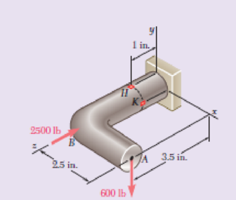
Forces are applied at points A and B of the solid cast-iron bracket shown. Knowing that the bracket has a diameter of 0.8 in., determine the principal stresses and the maximum shearing stress at (a) point H, (b) point K.
Fig. P8.72
(a)
The principal stresses and the maximum shearing stress at point H.
Answer to Problem 72RP
The maximum principal stress at point H is
The minimum principal stress at H is
The shear stress at point H is
Explanation of Solution
Given information:
The diameter (d) of the bracket is
Calculation:
Sketch the free body diagram of solid cast iron as shown in Figure 1.
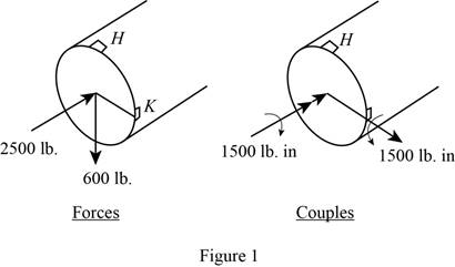
Refer to Figure 1.
Find the value of P at the section containing point H and K.
Find the shear force about y axis as follows:
Find the shear force about x axis as follows:
Find the moment about x axis as follows:
Find the moment about y axis as follows:
Find the moment about z axis as follows:
Find the value of radius (c) using the relation:
Here, d is the diameter of bracket.
Substitute
Find the area (A) of the circular section using the equation:
Here, c is the half of the diameter.
Substitute
Find the moment of inertia (I) of section using the relation:
Substitute
Find the moment of inertia (J) of section using the relation:
Substitute
Find the value of Q for semicircle using the relation:
Substitute
Determine the normal stress at point H using the relation:
Here, P is the centric force, A is the area of circular cross section, I is the moment of inertia, M is the moment, and c is the centroid distance.
Substitute
Determine the shear stress at point H using the relation:
Here, T is the Torque and J is the polar moment of inertia.
Substitute
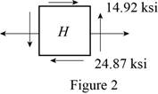
Sketch the stresses at point H as shown in Figure 2.
Find the average
Here, normal stress at point H.
Substitute
Find the R using the relation:
Here, shear stress at point H.
Substitute
Determine the maximum principal stress
Substitute
Thus, the maximum principal stress at point H is
Determine the minimum principal stress
Substitute
Thus, the minimum principal stress at H is
Determine the maximum shear stress at point H using the relation:
Here,
Substitute
Thus, the shear stress at point H is
(b)
The principal stresses and the maximum shearing stress at point K.
Answer to Problem 72RP
The maximum principal stress at point K is
The minimum principal stress at K is
The shear stress at point K is
Explanation of Solution
Calculation:
Determine the normal stress at point K using the relation:
Substitute
Determine the shear stress at point K using the relation:
Substitute
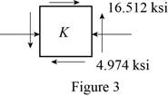
Sketch the stresses at point K as shown in Figure 3.
Find the average
Here, normal stress at point H.
Substitute
Find the R using the relation:
Here, shear stress at point H.
Substitute
Determine the maximum principal stress
Substitute
Thus, the maximum principal stress at point K is
Determine the minimum principal stress
Substitute
Thus, the minimum principal stress at K is
Determine the maximum shear stress at point K using the relation:
Here,
Substitute
Thus, the shear stress at point K is
Want to see more full solutions like this?
Chapter 8 Solutions
Loose Leaf For Mechanics Of Materials Format: Looseleaf


- Straight rods of 0.30-in. diameter and 200-ft length are sometimes used to clear underground conduits of obstructions or to thread wires through a new conduit. The rods are made of high-strength steel and, for storage and transportation, are wrapped on spools of 5-ft diameter. Assuming that the yield strength is not exceeded, determine (a) the maximum stress in a rod, when the rod, which was initially straight, is wrapped on the spool, (b) the corresponding bending moment in the rod. Use E= 29 * 106 psi.arrow_forwardFor the state of stress shown, it is known that the normal and shearing stresses are directed as shown and that σx = 15.5 ksi, σy = 9 ksi, and σmin = 5 ksi. Determine the orientation of the principal planes. Determine the principal stress σmax. Determine the maximum in plane shearing stressarrow_forwardA steel pipe of 400-mm outer diameter is fabricated from 10-mmthick plate by welding along a helix that forms an angle of 20° with a plane perpendicular to the axis of the pipe. Knowing that a 300-kN axial force P is applied to the pipe, determine the normal and shearing stresses in directions respectively normal and tangential to the weld.arrow_forward
- The storage tank shown contains liquefied propane under a pressure of 1.4 MPa at a temperature of 38 °C . Knowing that the tank has a diameter of 315 mm and a wall thickness of 2.8 mm determinethe maximum normal stress and the maximum shearing stress in the tank.arrow_forwardThe driveshaft of an automobile is being designed to transmit 238 hp at 3790 rpm. Determine the minimum diameter d required for a solid steel shaft if the allowable shear stress in the shaft is not to exceed 5700 psi.arrow_forwardA compressive member of a structure is of 25 mm square cross-section and carries a load of 50 kN. Determine, from first principles, the normal, tangential, and resultant stresses on a plane inclined at 60° to the axis of the bar.arrow_forward
- Two steel plates are to be held together by means of 16-mm-diameter high-strength steel bolts fitting snugly inside cylindrical brass spacers.Knowing that the average normal stress must not exceed 200 MPa in the bolts and 130 MPa in the spacers, determine the outer diameter of the spacers that yields the most economical and safe design.arrow_forwardA torque of 1.4KNm and two forces of 10kN and 12kN are applied to the top of a 65mm diameter solid steel post. Determine the principal stresses and the maximum shear stress at point H and point K.arrow_forwardA standard-weight steel pipe of 12-in. nominal diameter carries water under a pressure of 400 psi. (a) Knowing that the outside diameter is 12.75 in. and the wall thickness is 0.375 in., determine the maximum tensile stress in the pipe. (b) Solve part a, assuming that an extra-strong pipe is used, of 12.75-in. outside diameter and 0.5-in. wall thickness.arrow_forward
- A steel shaft and an aluminum tube are connected to a fixed support and to a rigid disk as shown in the cross section. Knowing that the initial stresses are zero, determine the maximum torque T0 that can be applied to the disk if the allowable stresses are 120 MPa in the steel shaft and 70 MPa in the aluminum tube. Use G= 77 GPa for steel and G = 27 GPa for aluminum.arrow_forwardShow that the angle between the plane of the major principal stress and the plane of the maximum shear stress is 45° for any state of stress.arrow_forwardAn offset h must be introduced into a metal tube of 0.75-in. outer diameter and 0.08-in. wall thickness. Knowing that the maximum stress after the offset is introduced must not exceed 4 times the stress in the tube when it was straight, determine the largest offset that can be used.arrow_forward
 Elements Of ElectromagneticsMechanical EngineeringISBN:9780190698614Author:Sadiku, Matthew N. O.Publisher:Oxford University Press
 Mechanics of Materials (10th Edition)Mechanical EngineeringISBN:9780134319650Author:Russell C. HibbelerPublisher:PEARSON
 Thermodynamics: An Engineering ApproachMechanical EngineeringISBN:9781259822674Author:Yunus A. Cengel Dr., Michael A. BolesPublisher:McGraw-Hill Education
 Control Systems EngineeringMechanical EngineeringISBN:9781118170519Author:Norman S. NisePublisher:WILEY
 Mechanics of Materials (MindTap Course List)Mechanical EngineeringISBN:9781337093347Author:Barry J. Goodno, James M. GerePublisher:Cengage Learning
 Engineering Mechanics: StaticsMechanical EngineeringISBN:9781118807330Author:James L. Meriam, L. G. Kraige, J. N. BoltonPublisher:WILEY