
Concept explainers
Videos
Programs DYNACAM and MATRIX may be used to solve these problems or to check your solution where appropriate.
Figure P8-1 shows the cam and follower from Problem 6-65. Using graphical methods, find and sketch the equivalent fourbar linkage for this position of the cam and follower.
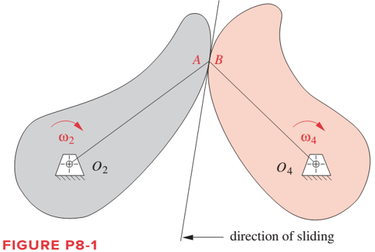
To sketch: The equivalent four bar linkage of thecam follower.
Explanation of Solution
Cams are rotated by cam pair at A and B. For an equivalent four bar linkage of cam and follower mechanism, the cam pair is converted into two turning pair by an imaginary link AB. Length of the link will be equal to the center of curvature distances between two cams. Also the two cam is replaced by a two links O2A and O2B. O2A is the distance between center of curvature of left cam at A and center of rotation of left cam at O2. Similarly O2B is distance between the center of curvature of right cam at B and center of rotation of right cam at O4.
Graphical method for four bar mechanism:-
- Take O2 and O4 as a fix link.
- Mark A and B as a center of curvature of the left and right cam respectively.
- Draw O2A and O2B and join A and B as AB.
Drawing the equivalent four bar linkage as shown below:
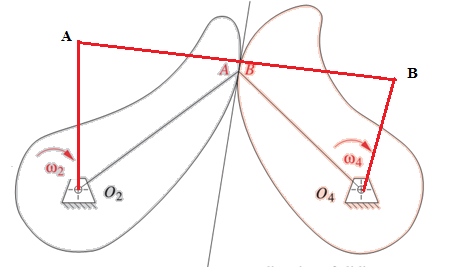
O2ABO4is the equivalent 4 bar linkage of two sliding cam mechanism. The angular velocity of left and right cam will be equal to the angular velocity of link O2A and O2B respectively.
Want to see more full solutions like this?
Chapter 8 Solutions
DESIGN OF MACHINERY (LL W/ CONNECT)


- Refer to the figure below for the mechanism.If link 2 rotates at a speed of 60 revolutions per minute, find the velocity, using resolution and composition method of: A point connecting link 2 to link 3 A point at the center of link 2 A point at the center of link 3 Of the slider Also, locate all the instantaneous centers. Use counterclockwise direction.arrow_forwardRefer to the figure below for the mechanism. If link 2 rotates at a speed of 60 revolutions per minute, find the velocity, using resolution and composition method of: A point connecting link 2 to link 3 A point at the center of link 2 A point at the center of link 3 Of the slider Also, locate all the instantaneous centers. Use counterclockwise direction.arrow_forwardRefer to the figure below for the mechanism. If link 2 rotates at a speed of 60 revolutions per minute in a counterclockwise direction , find the velocity, using resolution and composition method of: A point connecting link 2 to link 3 A point at the center of link 2 A point at the center of link 3 Of the slider Also, locate all the instantaneous centers.arrow_forward
- A cam drive is used for a mechanism incorporated in a shoe-sewing machine.The cam follower must rise outward 0.5 in. with cycloidal motion in 0.7 s, dwellfor 0.2 s, fall 0.25 in. with cycloidal motion in 0.5 s, dwell for 0.2 s, fall 0.25 in. withcycloidal motion in 0.5 s and then repeat the sequence. Determine therequired speed of the cam and graphically plot a follower displacementdiagram.arrow_forwardA cam drive is used for mechanism that drives an automated assembly machine. The cam follower must rise outward 13 mm with constant velocity in 3 sec, dwell for 3 sec, fall 5 mm with constant acceleration in 2 sec, and then repeat the sequence. Determine the following for the given problems: 1. Calculate the time for a full cycle 2. Calculate the required rotational speed of the cam 3. Determine the cam rotation for each follower motion interval 4. Plot the displacement diagramarrow_forwardAcceleration analysis of Scotch Yoke Mechanism To determine the acceleration of slotted slider for different crank lengths at different crank angles for various angular velocity theoretically by using the variables. Note; can you solve it as above for the following variables given in the imagearrow_forward
- Problem 4: A four bar linkage is shown below with crank Q2A, 1 foot long and crank 2 rotates clockwise with an instantaneous angular velocity of 152.79 rpm. The rest of the members are drawn to scale. Solve for the Velocity of point A and find the velocities of B, C, D, E and F using RESOLUTION AND COMPOSITION METHOD only! Ks = 1 inch : 1 foot Kv = 1 inch : 16 fpsarrow_forwardDesign a plate cam to give the following motion to a roller follower: raise 50 mm with uniform motion for 120 deg, dwell for 30 deg, return to its position with uniformly accelerated motion and retarded motion for 180 deg, and dwell for the remainder of the cycle. Use 110 mm base circle and a 20 mm roller. Cam rotates Counter clockwise. Scale is 1:1arrow_forwardPlease don't provide handwritten solution.... Please I need to see the whole procedure. There are many similar problems but they calculate the velocity or acceleration, I need to calculate the positions, the time ratio and the stroke of link 6.arrow_forward
- Find the average piston velocity (between limiting positions) for an in-line slider-crank mechanism. The crank length is 2inch, and the crank rotates at 3000rev/min.arrow_forwardGiven a cam motion 0 degrees to 90 degrees-dwell 90 degrees to 180 degrees- rise by 22mm using simple harmonic motion 180 degrees to 270°- dwell at 22mm 270 degrees to 360 degrees-fall by 22mm back to start position using simple harmonic Draw a rough sketch for the SVAJ Diagramarrow_forwardDraw the cam profile for a knife-edge follower having the followingmotion: rise 50 mm during 150 deg turn with gravitational motion, dwell for 30deg, fall 50 mm during 150 deg turn with gravitational motion, and dwell for 30deg. Use 100 mm base circle. Cam rotates clockwise. Scale 1:1arrow_forward
 Elements Of ElectromagneticsMechanical EngineeringISBN:9780190698614Author:Sadiku, Matthew N. O.Publisher:Oxford University Press
 Mechanics of Materials (10th Edition)Mechanical EngineeringISBN:9780134319650Author:Russell C. HibbelerPublisher:PEARSON
 Thermodynamics: An Engineering ApproachMechanical EngineeringISBN:9781259822674Author:Yunus A. Cengel Dr., Michael A. BolesPublisher:McGraw-Hill Education
 Control Systems EngineeringMechanical EngineeringISBN:9781118170519Author:Norman S. NisePublisher:WILEY
 Mechanics of Materials (MindTap Course List)Mechanical EngineeringISBN:9781337093347Author:Barry J. Goodno, James M. GerePublisher:Cengage Learning
 Engineering Mechanics: StaticsMechanical EngineeringISBN:9781118807330Author:James L. Meriam, L. G. Kraige, J. N. BoltonPublisher:WILEY