
Steel Design (Activate Learning with these NEW titles from Engineering!)
6th Edition
ISBN: 9781337094740
Author: Segui, William T.
Publisher: Cengage Learning
expand_more
expand_more
format_list_bulleted
Concept explainers
Videos
Textbook Question
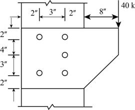
Chapter 8, Problem 8.2.3P
A plate is used as a bracket and is attached to a column flange, as shown in Figure P8.2-3. Use an elastic analysis and compute the maximum bolt shear force.
Expert Solution & Answer

Trending nowThis is a popular solution!

Students have asked these similar questions
f. Calculate the maximum safe load "P" in KN
Two A36 16mm Thick Steel Plates Are Connected By Four Rivets With Fv=152 MPa As Shown.
Given:
Rivet Dia 20 mm
x=100 mm
A 19-mm-diameter steel [E = 202 GPa: 0 = 11.1x10⁻⁶/°C] bolt is used to connect two rigid parts of an assembly. The bolt length is a =
175 mm. Determine the minimum clamping force that must be provided by the bolt when T1 = 21°C so that the clamping force it exerts
when T2 = 58°C is at least 2.1 kN.
Determine the Ultimate Moment Capacity of the given section with the following properties
f'c=28 MPa
fy=345 MPa
Steel cover =d'=60mm
Chapter 8 Solutions
Steel Design (Activate Learning with these NEW titles from Engineering!)
Ch. 8 - Prob. 8.2.1PCh. 8 - Prob. 8.2.2PCh. 8 - A plate is used as a bracket and is attached to a...Ch. 8 - Prob. 8.2.4PCh. 8 - Prob. 8.2.5PCh. 8 - Prob. 8.2.6PCh. 8 - Prob. 8.2.7PCh. 8 - Prob. 8.2.8PCh. 8 - Prob. 8.2.9PCh. 8 - Prob. 8.2.10P
Ch. 8 - Prob. 8.2.11PCh. 8 - Prob. 8.2.12PCh. 8 - Prob. 8.2.13PCh. 8 - Prob. 8.3.1PCh. 8 - Prob. 8.3.2PCh. 8 - Prob. 8.3.3PCh. 8 - Prob. 8.3.4PCh. 8 - Prob. 8.3.5PCh. 8 - Prob. 8.3.6PCh. 8 - Prob. 8.3.7PCh. 8 - Prob. 8.3.8PCh. 8 - Prob. 8.3.9PCh. 8 - Prob. 8.3.10PCh. 8 - Use an elastic analysis and determine the maximum...Ch. 8 - Use an elastic analysis and determine the maximum...Ch. 8 - Use an elastic analysis and determine the maximum...Ch. 8 - Prob. 8.4.4PCh. 8 - Prob. 8.4.5PCh. 8 - Prob. 8.4.6PCh. 8 - Use an elastic analysis and compute the extra load...Ch. 8 - Use an elastic analysis and compute the extra load...Ch. 8 - Prob. 8.4.9PCh. 8 - Prob. 8.4.10PCh. 8 - Prob. 8.4.11PCh. 8 - Prob. 8.4.12PCh. 8 - Prob. 8.4.13PCh. 8 - Prob. 8.4.14PCh. 8 - Prob. 8.4.15PCh. 8 - Prob. 8.4.16PCh. 8 - Prob. 8.4.17PCh. 8 - Prob. 8.4.18PCh. 8 - a. Use LRFD and design a welded connection for the...Ch. 8 - Prob. 8.4.20PCh. 8 - Prob. 8.5.1PCh. 8 - Prob. 8.5.2PCh. 8 - Prob. 8.5.3PCh. 8 - Prob. 8.5.4PCh. 8 - Prob. 8.5.5PCh. 8 - Prob. 8.6.1PCh. 8 - Prob. 8.6.2PCh. 8 - Prob. 8.6.3PCh. 8 - Prob. 8.6.4PCh. 8 - Prob. 8.7.1PCh. 8 - Prob. 8.7.2PCh. 8 - Prob. 8.7.3PCh. 8 - Prob. 8.8.1PCh. 8 - Prob. 8.8.2PCh. 8 - Prob. 8.8.3PCh. 8 - Prob. 8.8.4P
Knowledge Booster


Learn more about
Need a deep-dive on the concept behind this application? Look no further. Learn more about this topic, civil-engineering and related others by exploring similar questions and additional content below.Similar questions
- a rigid bar (ABCD) which was supported thru pin at B. Two bars was also connected, Bar CE and Bar DF with corresponding cross-sectional area and Modulus of Elasticity. If P is equivalent to 94 kN, the diameter at pin B is Blank 1 mm.arrow_forwardFind; -Is a W12 x 14 adequate for the purlins considering moment, shear and deflection? 0 -If a W10 x 12 is used for the purlins, compute the allowable moment strength for the y-axis in KN.m. 0 -Select the lightest W-shape for the purlins considering moment, shear and deflection.0arrow_forwardA 18-mm-diameter steel (E = 194 GPa: C = 12.3x10⁻⁶/°C] bolt is used to connect two rigid parts of an assembly. The bolt length is a = 120 mm. Determine the minimum clamping force that must be provided by the bolt when T1 = 19°C so that the clamping force it exerts when T2 = 62°C is at least 1.9 kN.arrow_forward
- Subject : Steel design 1. A tension number is an angular section 150mm x 110mm x 12.5 mm having a cross sectional area of 3064mm^2. The section is connected with three 18mm diameter bolt spaced at 100mm on centers as shown on the figure.Minimum tensile strength Fu=400Mpa and Fy=248.8Mpa. Diameter of Hole is 21mm. a. Compute the block shearing strength of the member.arrow_forwardEx: For a cantilever beam of length (L) subject 1 a concentrated load (P), shown in fgure, Find - 1 Max.tension and compression bending stress in beam section 2. Determine the proper spacing of the nails used 10 fix the flange boards to the web. The nals o be used can safely resist (F) of shearing force, given in 3 - “Table below. I»arrow_forwardI am ok with parts a) and c) but regarding the part b) I think we should mention the number of loops so the equation should be : SI = ext + int - releases = react. - (3 equ) + (3 equ) ( nb of loops) - releases ( no hinges here )= (4) - (3) + (3)(1) - 0 = 4h degree and if I used the simple method, I brake the frame into 2 membersso r= 2+2+3+3=10 n= 2 membersso r> 3n by 4 degree Does it make sense?arrow_forward
- A C7x9.8 tension member (A36) is connected to a 3/8-inch thick gusset plate (A36) as shown below. Compute the available block shear strenghth of the gusset plate for both LRFD and ASDarrow_forwardFor the clevis connection shown, determine the shear stress in the 20-mm-diameter bolt for an applied load of P = 130 kN.arrow_forwardProb 01: An 18” depth beam is bolted to a 24” depth girder is connected similar to that in figure shown below. Thediameter of the rivet is 20mm and the angles are each 100mm x 100mm x 12mm thick. For each bolt, assume thatthe allowable bearing stress is 220 MPa. Determine the allowable load P in KN on the connection. *show all theload P in kN for bearing stressBeam web thickness = 5mmGirder web thickness =arrow_forward
- A WT10.5 x 31 is used as a bracket to transmit a 60-kip service load to a W14 x 90 column, as previously shown in Figure . The load consists of 15 kips dead load and 45 kips live load. Four 7⁄8-inch-diameter Group A bolts are used. The column is of A992 steel, and the bracket is A36. Assume all spacing and edge-distance requirements are satisfied, including those necessary for the use of the nominal strength in bearing deformation (i.e., 2.4dtFu)*, and determine the adequacy of the bolts for the following types of connections: (a) bearing-type connection with the threads in shear and (b) slip-critical connection with the threads in shear.arrow_forwardPROBLEM: The forces in each member are used by method discussed in your theory of structures/mechanics. Use Pn = 205 kN, Po = 0. a) From the Problem and the image , Design one tension member, use either a double angle of a wt section. Check its adequacy using 1 line of bolts (three bolts in a line spaced at 75mm on centers) Assume a bolt diameter from 16-22mm. Use A 36 for all steel. Neglect block shear.arrow_forwardA plate 1⁄2 3 4 of A36 steel is used as a tension member to carry a service dead load of 6 kips and a service live load of 18 kips. It is to be attached to a 3⁄8-inch gusset plate, as shown in Figure. Design a welded connection.arrow_forward
arrow_back_ios
SEE MORE QUESTIONS
arrow_forward_ios
Recommended textbooks for you
 Steel Design (Activate Learning with these NEW ti...Civil EngineeringISBN:9781337094740Author:Segui, William T.Publisher:Cengage Learning
Steel Design (Activate Learning with these NEW ti...
Civil Engineering
ISBN:9781337094740
Author:Segui, William T.
Publisher:Cengage Learning
Material Properties 101; Author: Real Engineering;https://www.youtube.com/watch?v=BHZALtqAjeM;License: Standard YouTube License, CC-BY