
Concept explainers
(a)
To sketch:The safe operating area for the transistor and the load line on the same graph.
(a)
Answer to Problem 8.5P
Thearea for the safe operation of the transistor and the load line for the transistor is shown in Figure 1.
Explanation of Solution
Calculation:
The sketch for the safe operating area of the transistor is shown below.
The required diagram is shown in Figure 1
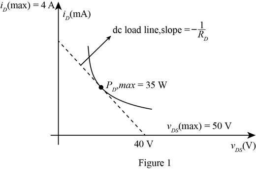
The above figure shows the safe region under which the transistor must be operated. The graph is plotted under the linear current and voltage scale. The sketch for the load line is dotted and is given by
Conclusion:
Therefore, the area for the safe operation of the transistor and the load line for the transistor is shown in Figure 1
(b)
The value of the drain current.
(b)
Answer to Problem 8.5P
Thepower at
Explanation of Solution
Calculation:
The expression for the voltage
The expression for the drain current is given by,
Substitute
The expression for the drain to source voltage is given by,
Substitute
The expression for the power dissipation is given by,
Substitute
Substitute
Substitute
Substitute
Substitute
Substitute
Substitute
The expression for the drain current in the non saturated region is given by,
Substitute
The expression for the drain current by ohm’s law is given by,
Substitute
Substitute
Substitute
Substitute
Substitute
Substitute
Substitute
Substitute
Conclusion:
Therefore, the power at
(c)
Whether there is a possibility of transistor getting damage.
(c)
Answer to Problem 8.5P
Yes, thetransistor will get damaged at
Explanation of Solution
The power of the transistor at
The above power is greater than the rated power of the transistor this means that the transistor gets damaged at
Want to see more full solutions like this?
Chapter 8 Solutions
Microelectronics Circuit Analysis and Design


- 8. Describe what are the components that has been employed, and their specific role for the provided problem below.arrow_forwardI need the DC analysis for this circuit, hence IC, IE, IB, VB, VC and VE Assume Beta to be 200, capacitors are open circuits in DC analysis and please make a clear explanation of the mode of operationarrow_forwardAsap Solve and recheck by using another circuit analysis method.arrow_forward
- Discuss the Combinational Circuitsarrow_forwardCreate a circuit of the Combinational Networks of the combination of BJT and FET with AC and DC supply. Solve it and show complete solution.arrow_forwardELECTRONIC CIRCUIT ANALYSIS AND DESIGN Please give the step-by-step solution for this problem. Thank you! Note: Neglect Vbearrow_forward
- The output curve of the circuit in the photo is given. Since the points where the curve intersects the Vo axis are +10 and -10, the points where the Vg axis intersects are +7.61 and -7.61, find the resistance of R1 in ohms. (opamp is ideal)arrow_forwardSketch the equivalent circuitarrow_forwardGiven the following details: The inverting adder schematic as seen below Vac is an AC voltage source which generates a sine waveform with amplitude 1mV and frequency 1kHz Vout is a sine waveform with amplitude 1V and has a DC offset of 3.5V Find the values of Vdc, R1, R2 and Rf that would satisfy the description for Vout. Assume ideal scenario (i.e. do theoretical computations instead of practical simulations)arrow_forward
- Select appropriate components using standard5 percent resistor values to obtain a gain of magnitudeapproximately equal to 1,000 in the circuit of FigureP8.44. Compute the error in the gain, assuming that the5 percent tolerance resistors have the nominal value. Use the ±5 percent tolerance range to compute the possible range of gains for this amplifierarrow_forwardConsider the following circuit. Calculate the output voltage when VGS=0 and VGS=-10V. Also, calculate the on-off ratio.arrow_forwardDuring circuit design process,what are some general technical dilemmas faced by engineers?Explain how an engineer can arrive at an optimal solution given the requirements of a customer.arrow_forward
 Introductory Circuit Analysis (13th Edition)Electrical EngineeringISBN:9780133923605Author:Robert L. BoylestadPublisher:PEARSON
 Delmar's Standard Textbook Of ElectricityElectrical EngineeringISBN:9781337900348Author:Stephen L. HermanPublisher:Cengage Learning
 Programmable Logic ControllersElectrical EngineeringISBN:9780073373843Author:Frank D. PetruzellaPublisher:McGraw-Hill Education
 Fundamentals of Electric CircuitsElectrical EngineeringISBN:9780078028229Author:Charles K Alexander, Matthew SadikuPublisher:McGraw-Hill Education
 Electric Circuits. (11th Edition)Electrical EngineeringISBN:9780134746968Author:James W. Nilsson, Susan RiedelPublisher:PEARSON
 Engineering ElectromagneticsElectrical EngineeringISBN:9780078028151Author:Hayt, William H. (william Hart), Jr, BUCK, John A.Publisher:Mcgraw-hill Education,