
TEXTBOOK OF ELECTRICITY W/MINDTAP >BI<
6th Edition
ISBN: 9781305812505
Author: Herman
Publisher: Cengage Learning
expand_more
expand_more
format_list_bulleted
Concept explainers
Videos
Textbook Question
Chapter 8, Problem 9PP
Find the missing values for the circuit shown in Figure 8-27.
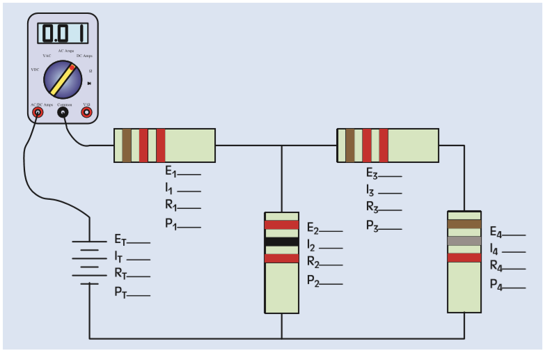
FIGURE 8-27 Combination circuit.
Expert Solution & Answer
Want to see the full answer?
Check out a sample textbook solution
Students have asked these similar questions
What are the expected voltages at points C and D of this circuit?
What are some applications for a series-parallel circuit? Choose one of the applications and tell everyone why a series-parallel circuit is used for the application instead of just a series or parallel circuit.
State Kirchoff's current Law.
None of these
sum of all powers in a circuit
sum of all emfs in a circuit
sum of all positive currents is equal to
sum of all negative currents.
sum of all positive voltages is equal to
the sum of all negative voltages
taken in order
Chapter 8 Solutions
TEXTBOOK OF ELECTRICITY W/MINDTAP >BI<
Ch. 8 - Referto Figure 8-2. Replace the values shown with...Ch. 8 - 2. Refer to Figure 8-5. Replace the values shown...Ch. 8 - 3. Refer to the circuit shown in Figure 8-2....Ch. 8 - Refer to the circuit shown in Figure 6-22. The...Ch. 8 - Refer to Figure 8-21. Assume that the resistors...Ch. 8 - A circuit contains a 1000- and a 300- resistor...Ch. 8 - Two resistors are connected in series. One...Ch. 8 - A single-phase electric motor is connected to a...Ch. 8 - The hot water for the heating system for a small...Ch. 8 - Find the unknown values in the circuit if the...
Ch. 8 - Refer to the circuit shown in Figure 8-21 to solve...Ch. 8 - 3. Find the unknown values in the circuit if the...Ch. 8 - Refer to the circuit shown in Figure 8-25 to solve...Ch. 8 - 5. Find the unknown values in the circuit if the...Ch. 8 - Find the unknown values in the circuit if the...Ch. 8 - Refer to the circuit shown in Figure 8-26 to solve...Ch. 8 - ET E1 E2 E3 E41.248V IT I1 I2 I3 I4 RT R1 R2 R3 R4...Ch. 8 - Find the missing values for the circuit shown in...Ch. 8 - Find the missing values for the circuit shown in...
Knowledge Booster


Learn more about
Need a deep-dive on the concept behind this application? Look no further. Learn more about this topic, electrical-engineering and related others by exploring similar questions and additional content below.Similar questions
- what is the practical utility of this circuitarrow_forwardC. PROCEDURES 1. Connect the circuit as shown in Figure 7-1. 2. Measure and record the voltage and currents assigned in Table 7-1, 7-2, 7-3 and 7-4. 3. Determine the total voltage and current in each row. 4. Compute for the values of current and voltages using Kirchhoff's Laws and compute the percent difference. D. CIRCUIT DIAGRAM A R2 B + 1000 - IT 150 100 V2 I50 175 R1 1500 + V3 R3 750 R4 V4 12V V1 502 D FIGURE 7arrow_forwardWhat are the expected voltages of C and D of this circuit?arrow_forward
- An ammeter is a tool that measures the current (a better name would be V Show Current O Electrons ampmeter) that passes through it. In the circuit simulation you can get Conventional ammeters from the upper right toolbar. Labels Values When current is flowing in through the meter a number value will replace the question mark. Current Votmeter Ammeters Wire Resistivity First make a simple series circuit with a battery, switch, single light bulb and ammeter as shown at right. It's actually not necessary to include the switch but if I left it out then my snapshots would all give away the answers. With the switch closed/current flowing in the circuit, record the current that Current is flowing out of the light bulb and back to the battery. 0.00 A The current is A Now switch the light bulb and the battery so that the ammeter comes before the bulb. Current 0.00 A With the switch closed/current flowing in the circuit, record the current that is flowing out of the battery and into the light…arrow_forwardUsing the rules for parallel circuits and Ohmslaw, solve for the missing values. ETE1E2E3E4ITl1I2l33.2AI4RT3.582R116R210R3R420PTP1P2P3P4arrow_forwardwhat is the Definition of electrical series circuits and Definition of electrical parallel circuits ?arrow_forward
- Reduce this combination circuit and find current and voltage in each resistor. Start with reducing ones circled first, then continue process.arrow_forwardMy question is the Ri does mean the resistance inside the voltage source or just an addition resestor that out side just to resist the voltage ??arrow_forwardFind the current in each resistor using source transformation and nodal analysis. **SKIP IO AND VO**arrow_forward
arrow_back_ios
SEE MORE QUESTIONS
arrow_forward_ios
Recommended textbooks for you
 Delmar's Standard Textbook Of ElectricityElectrical EngineeringISBN:9781337900348Author:Stephen L. HermanPublisher:Cengage Learning
 Electricity for Refrigeration, Heating, and Air C...Mechanical EngineeringISBN:9781337399128Author:Russell E. SmithPublisher:Cengage Learning
Delmar's Standard Textbook Of Electricity
Electrical Engineering
ISBN:9781337900348
Author:Stephen L. Herman
Publisher:Cengage Learning
Electricity for Refrigeration, Heating, and Air C...
Mechanical Engineering
ISBN:9781337399128
Author:Russell E. Smith
Publisher:Cengage Learning
Current Divider Rule; Author: Neso Academy;https://www.youtube.com/watch?v=hRU1mKWUehY;License: Standard YouTube License, CC-BY