
Mastering Engineering with Pearson eText -- Standalone Access Card -- for Mechanics of Materials
10th Edition
ISBN: 9780134321288
Author: HIBBELER
Publisher: PEARSON
expand_more
expand_more
format_list_bulleted
Concept explainers
Videos
Textbook Question
Chapter 8.1, Problem 8.14P
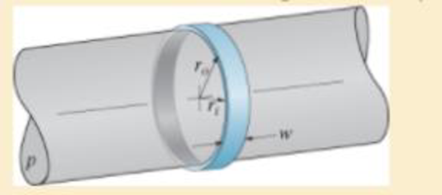
The ring, having the dimensions shown, is placed over a flexible membrane which is pumped up with a pressure p. Determine the change in the inner radius of the ring after this pressure is applied. The modulus of elasticity for the ring is E.
Expert Solution & Answer
Want to see the full answer?
Check out a sample textbook solution
Students have asked these similar questions
The ring, having the dimensions shown, is placed over a flexible membrane which is pumped up with a pressure p. Determine the change in the inner radius of the ring after this pressure is applied. The modulus of elasticity for the ring is E.
If the bucket weights 50 lb, determine thetension developed in each of the wires.
Cords are looped around a small spacer separating two cylinder each weighing 400kn and pass over a frictionless pulleys to weights of 200KN and 400kn. Determine the angle and the pressure N between the cylinder and smooth horizontal surface
Chapter 8 Solutions
Mastering Engineering with Pearson eText -- Standalone Access Card -- for Mechanics of Materials
Ch. 8.1 - If it is subjected to an internal pressure of p =...Ch. 8.1 - If it is subjected to an internal pressure of p =...Ch. 8.1 - The thin-walled cylinder can be supported in one...Ch. 8.1 - If the inner diameter of the tank is 22 in., and...Ch. 8.1 - Air pressure in the cylinder is increased by...Ch. 8.1 - Determine the maximum force P that can be exerted...Ch. 8.1 - A boiler is constructed of 8-mm-thick steel plates...Ch. 8.1 - 88. The steel water pipe has an inner diameter of...Ch. 8.1 - The steel water pipe has an inner diameter of 12...Ch. 8.1 - The A-36-steel band is 2 in. wide and is secured...
Ch. 8.1 - The gas pipe line is supported every 20 ft by...Ch. 8.1 - A pressure-vessel head is fabricated by welding...Ch. 8.1 - An A-36-steel hoop has an inner diameter of 23.99...Ch. 8.1 - The ring, having the dimensions shown, is placed...Ch. 8.1 - The inner ring A has an inner radius r1 and outer...Ch. 8.1 - Two hemispheres having an inner radius of 2 ft and...Ch. 8.1 - In order to increase the strength of the pressure...Ch. 8.2 - Show the results on the left segment.Ch. 8.2 - Show the stress that each of these loads produce...Ch. 8.2 - Fundamental Problems F81. Determine the normal...Ch. 8.2 - Show the results in a differential element at the...Ch. 8.2 - Determine the state of stress at point A on the...Ch. 8.2 - Determine the magnitude of the load P that will...Ch. 8.2 - Determine the state of stress at point B. Show the...Ch. 8.2 - Determine the state of stress at point A on the...Ch. 8.2 - Determine the state of stress at point A on the...Ch. 8.2 - Show the results in a differential element at the...Ch. 8.2 - Determine the shortest distance d to the edge of...Ch. 8.2 - The plate has a thickness of 20 mm and P acts...Ch. 8.2 - Plot the distribution of normal stress acting...Ch. 8.2 - Also, plot the normal-stress distribution over the...Ch. 8.2 - If the allowable normal stress for the steel is...Ch. 8.2 - If the applied force P = 1.50 kip, determine the...Ch. 8.2 - Determine the maximum normal stress on the cross...Ch. 8.2 - If the wood has an allowable normal stress of...Ch. 8.2 - Determine the maximum normal stress along section...Ch. 8.2 - Sketch the stress distribution along section aa of...Ch. 8.2 - Sketch the normal-stress distribution acting over...Ch. 8.2 - Determine the state of stress at points A and B,...Ch. 8.2 - If the force of 100 N is applied to the handles,...Ch. 8.2 - Determine the stress components at point A on the...Ch. 8.2 - Determine the stress components at point B on the...Ch. 8.2 - Determine the normal stress developed at points A...Ch. 8.2 - Sketch the normal-stress distribution acting over...Ch. 8.2 - Determine the state of stress at points A and B,...Ch. 8.2 - Determine the state of stress at point A on the...Ch. 8.2 - Determine the state of stress at point B on the...Ch. 8.2 - Determine the state of stress acting at point D....Ch. 8.2 - Determine the state of stress acting at point E....Ch. 8.2 - If it is subjected to the force system shown,...Ch. 8.2 - Solve Prob.840 for point B.Ch. 8.2 - Determine the stress components acting on the...Ch. 8.2 - Determine the stress components acting on the...Ch. 8.2 - Neglect the weight of the block.Ch. 8.2 - Neglect the weight of the block.Ch. 8.2 - He is supported uniformly by two bars, each having...Ch. 8.2 - Determine the state of stress at point A, and show...Ch. 8.2 - Determine the state of stress at point B, and show...Ch. 8.2 - Determine the state of stress at point C, and show...Ch. 8.2 - Determine the maximum radius e at which the load P...Ch. 8.2 - Specify the region to which this load can be...Ch. 8.2 - Determine the smallest force P that can be applied...Ch. 8.2 - The coiled spring is subjected to a force P. If we...Ch. 8.2 - The pins at C and D are at the same location as...Ch. 8.2 - Determine the state of stress at point A, and show...Ch. 8.2 - Determine the state of stress at point B, and show...Ch. 8.2 - Determine the stress components at points A and B...Ch. 8.2 - Determine the stress components at points C and D...Ch. 8.2 - Determine the stress components in the support...Ch. 8.2 - Determine the stress components in the support...Ch. 8.2 - If the force at the ram on the clamp at D is P= 8...Ch. 8.2 - Determine the maximum ram force P that can be...Ch. 8.2 - and an outer radius of 3.00 in. If the face of the...Ch. 8.2 - for points E and F.Ch. 8.2 - Determine the stress components at points A and B...Ch. 8.2 - Solve Prob.8-65 for points C and D.Ch. 8.2 - Due to internal gearing, this causes the block to...Ch. 8.2 - Determine the state of stress at point A and show...Ch. 8.2 - Solve Prob.868 for point B.Ch. 8.2 - Determine the stress components at point A. Sketch...Ch. 8.2 - for the stress components at point B.Ch. 8.2 - Determine the state of stress at point A at...Ch. 8.2 - Determine the state of stress at point B at...Ch. 8 - If it supports a cable loading of 800 lb,...Ch. 8 - Determine the state of stress at point E on the...Ch. 8 - Determine the state of stress at point F on the...Ch. 8 - The suspender arm AE has a square cross-sectional...Ch. 8 - If the cross section of the femur at section aa...Ch. 8 - If it has a mass of 5 kg/m, determine the largest...Ch. 8 - and is used to support the vertical reactions of...Ch. 8 - and is used to support the vertical reactions of...
Knowledge Booster


Learn more about
Need a deep-dive on the concept behind this application? Look no further. Learn more about this topic, mechanical-engineering and related others by exploring similar questions and additional content below.Similar questions
- The 3 × 4-m side of an open tank is hinged at its bottom A and is held in place by a thin rod BC. The tank is to be filled with glycerine with a density of 1263 kg/m3 . Determine the force T in the rod and the reaction at the hinge after the tank is filled to a depth of 2.9 m.arrow_forwardThe cylinder having a diameter 2.5 ft weighs 57 lb and is 6 ft long. Determine the reaction (lb.) at A neglecting friction. Determine the reaction at B (lb.) neglecting friction. Weight density of water is 62.4 lb/ft3 Sp.gr Gs = 1.6arrow_forwardA crane is used to lower weights into a lake for an underwater construction project. Determine the tension in the rope of the crane due to a 3-ft-diameter spherical steel block (density = 494 lbm/ft3) when it is (a) suspended in the air and (b) completely immersed in water.arrow_forward
- I need to draw a free body diagram and the solution L=10marrow_forwardIf the maximum tension either rope can sustain without breaking is 4700 N, determine the maximum value of the hanging weight that these ropes can safely support. You can ignore the weight of the ropes and the steel cable.arrow_forwardA 50-m steel surveying tape has a mass of 1.6 kg. If the tape is stretched between two points at the same elevation and pulled until the tension at each end is 60 N, determine the horizontal distance between the ends of the tape. Neglect the elongation of the tape due to the tension.arrow_forward
- Horizontal plates are connected to the bar AB whose length varies linearly from zero to HA, as shown. The total weight of the set of plates is W. Determine: The maximum shear stress in member AB and the torsional rotation at point B. The diameter of member AB is equal to d and its shear modulus is G.arrow_forwardThe blade of the bulldozer shown below is rigidly attached to a linkage consisting of the arm AB, which is controlled by the hydraulic cylinder BC. There is an identical linkage on the other side of the bulldozer. Applied loads shown are for both linkages and F = 581 kN. Determine the pressure in hydraulic cylinder BC in Pa if the cylinder has a diameter of 80 mm.arrow_forwardThe self regulating flood gate A B C, pinned at B, is pressed against the lip of the spillway at C by the action of the 3645-N weight A. If the gate is to open when the water level reaches a height h = 6m, determine the distance x locating the weight A. Neglect the weight of the gate.arrow_forward
- Each of the three gates has a constant width 1: (perpendicular to the paper). Calculate the force P required to maintain each gate in the position shown. Express your answers in terms of b, c, h, and (the weight density of the fluid).arrow_forwardThe horizontal boom carries the weight W=108lb at A. The boom is supported by the cables AB and AC. The tensions in the cables are TAB=120lb and TAC=160lb. Determine the single force R that is equivalent to three forces acting on the boom at A.arrow_forwardDetermine the force F required to pull up the 3.54m stopper from the drain of a sink if the depth of water is 10 in. Use =0.036lb/in.3 for water and neglect the weight of the chain.arrow_forward
arrow_back_ios
SEE MORE QUESTIONS
arrow_forward_ios
Recommended textbooks for you
 International Edition---engineering Mechanics: St...Mechanical EngineeringISBN:9781305501607Author:Andrew Pytel And Jaan KiusalaasPublisher:CENGAGE L
International Edition---engineering Mechanics: St...
Mechanical Engineering
ISBN:9781305501607
Author:Andrew Pytel And Jaan Kiusalaas
Publisher:CENGAGE L
Pressure Vessels Introduction; Author: Engineering and Design Solutions;https://www.youtube.com/watch?v=Z1J97IpFc2k;License: Standard youtube license