
MECHANICS OF MATERIALS-W/CONNECT
15th Edition
ISBN: 9781308475998
Author: BEER
Publisher: MCG CUSTOM
expand_more
expand_more
format_list_bulleted
Videos
Textbook Question
Chapter 8.2, Problem 19P
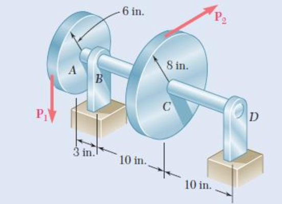
The vertical force P1 and the horizontal force P2 are applied as shown to disks welded to the solid shaft AD. Knowing that the diameter of the shaft is 1.75 in. and that τall = 8 ksi, determine the largest permissible magnitude of the force P2.
Fig. P8.19
Expert Solution & Answer
Want to see the full answer?
Check out a sample textbook solution
Students have asked these similar questions
In the structure shown, an 8-mm diameter pin is used at A, and 12- mm diameter pins are used at B and D. Knowing that the ultimate shearing stresses is 100 MPa at all connections and that the ultimate normal stress is 250 MPa in each of the two links joining B and D, determine the allowable load P if an overall factor of safety of 3.0 is desired.
Two steel plates are to be held together by means of 16-mm-diameter high-strength steel bolts fitting snugly inside cylindrical brass spacers.Knowing that the average normal stress must not exceed 200 MPa in the bolts and 130 MPa in the spacers, determine the outer diameter of the spacers that yields the most economical and safe design.
Two steel plates are to be held together by means of 16-mm-diameter high-strength steel bolts fitting snugly inside cylindrical brass spacers. Knowing that the average normal stress must not exceed 205 MPa in the bolts and 132 MPa in the spacers, determine the outer diameter of the spacers that yields the most economical and safe design.
The outer diameter of the spacers that yields the most economical and safe design is mm.
Chapter 8 Solutions
MECHANICS OF MATERIALS-W/CONNECT
Ch. 8.2 - A W10 = 39 rolled-steel beam supports a load P as...Ch. 8.2 - Solve Prob. 8.1, assuming that P = 22.5 kips and a...Ch. 8.2 - An overhanging W920 449 rolled-steel beam...Ch. 8.2 - Solve Prob. 8.3, assuming that P = 850 kN and a =...Ch. 8.2 - 8.5 and 8.6 (a) Knowing that all = 160 MPa and all...Ch. 8.2 - 8.5 and 8.6 (a) Knowing that all = 160 MPa and all...Ch. 8.2 - 8.7 and 8.8 (a) Knowing that all = 24 ksi and all...Ch. 8.2 - 8.7 and 8.8 (a) Knowing that all = 24 ksi and all...Ch. 8.2 - 8.9 through 8.14 Each of the following problems...Ch. 8.2 - 8.9 through 8.14 Each of the following problems...
Ch. 8.2 - 8.9 through 8.14 Each of the following problems...Ch. 8.2 - Prob. 12PCh. 8.2 - 8.9 through 8.14 Each of the following problems...Ch. 8.2 - 8.9 through 8.14 Each of the following problems...Ch. 8.2 - Determine the smallest allowable diameter of the...Ch. 8.2 - Determine the smallest allowable diameter of the...Ch. 8.2 - Using the notation of Sec. 8.2 and neglecting the...Ch. 8.2 - The 4-kN force is parallel to the x axis, and the...Ch. 8.2 - The vertical force P1 and the horizontal force P2...Ch. 8.2 - The two 500-lb forces are vertical and the force P...Ch. 8.2 - Prob. 21PCh. 8.2 - Prob. 22PCh. 8.2 - The solid shaft AB rotates at 600 rpm and...Ch. 8.2 - The solid shaft AB rotates at 600 rpm and...Ch. 8.2 - The solid shafts ABC and DEF and the gears shown...Ch. 8.2 - Prob. 26PCh. 8.2 - Prob. 27PCh. 8.2 - Prob. 28PCh. 8.2 - The solid shaft AE rotates at 600 rpm and...Ch. 8.2 - The solid shaft AE rotates at 600 rpm and...Ch. 8.3 - Two 1.2-kip forces are applied to an L-shaped...Ch. 8.3 - Two 1.2-kip forces are applied to an L-shaped...Ch. 8.3 - The cantilever beam AB has a rectangular cross...Ch. 8.3 - 8.34 through 8.36 Member AB has a uniform...Ch. 8.3 - 8.34 through 8.36 Member AB has a uniform...Ch. 8.3 - 8.34 through 8.36 Member AB has a uniform...Ch. 8.3 - Prob. 37PCh. 8.3 - Two forces are applied to the pipe AB as shown....Ch. 8.3 - Several forces are applied to the pipe assembly...Ch. 8.3 - The steel pile AB has a 100-mm outer diameter and...Ch. 8.3 - Three forces are applied to a 4-in.-diameter plate...Ch. 8.3 - The steel pipe AB has a 72-mm outer diameter and a...Ch. 8.3 - A 13-kN force is applied as shown to the...Ch. 8.3 - A vertical force P of magnitude 60 lb is applied...Ch. 8.3 - Three forces are applied to the bar shown....Ch. 8.3 - Prob. 46PCh. 8.3 - Three forces are applied to the bar shown....Ch. 8.3 - Three forces are applied to the bar shown....Ch. 8.3 - Two forces are applied to the small post BD as...Ch. 8.3 - Two forces are applied to the small post BD as...Ch. 8.3 - Three forces are applied to the machine component...Ch. 8.3 - Prob. 52PCh. 8.3 - Three steel plates, each 13 mm thick, are welded...Ch. 8.3 - Three steel plates, each 13 mm thick, are welded...Ch. 8.3 - Two forces P1 and P2 are applied as shown in...Ch. 8.3 - Two forces P1 and P2 are applied as shown in...Ch. 8.3 - Prob. 57PCh. 8.3 - Four forces are applied to a W8 28 rolled-steel...Ch. 8.3 - A force P is applied to a cantilever beam by means...Ch. 8.3 - Prob. 60PCh. 8.3 - A 5-kN force P is applied to a wire that is...Ch. 8.3 - Knowing that the structural tube shown has a...Ch. 8.3 - The structural tube shown has a uniform wall...Ch. 8.3 - The structural tube shown has a uniform wall...Ch. 8 - (a) Knowing that all = 24 ksi and all = 14.5 ksi,...Ch. 8 - Neglecting the effect of fillets and of stress...Ch. 8 - Knowing that rods BC and CD are of diameter 24 mm...Ch. 8 - The solid shaft AB rotates at 450 rpm and...Ch. 8 - A 6-kip force is applied to the machine element AB...Ch. 8 - A thin strap is wrapped around a solid rod of...Ch. 8 - A close-coiled spring is made of a circular wire...Ch. 8 - Forces are applied at points A and B of the solid...Ch. 8 - Knowing that the bracket AB has a uniform...Ch. 8 - For the post and loading shown, determine the...Ch. 8 - Knowing that the structural tube shown has a...Ch. 8 - The cantilever beam AB will be installed so that...
Knowledge Booster


Learn more about
Need a deep-dive on the concept behind this application? Look no further. Learn more about this topic, mechanical-engineering and related others by exploring similar questions and additional content below.Similar questions
- A standard-weight steel pipe of 12-in. nominal diameter carries water under a pressure of 400 psi. (a) Knowing that the outside diameter is 12.75 in. and the wall thickness is 0.375 in., determine the maximum tensile stress in the pipe. (b) Solve part a, assuming that an extra-strong pipe is used, of 12.75-in. outside diameter and 0.5-in. wall thickness.arrow_forwardIn the structure shown, an 8-mm diameter pin is used at A, and 12-mm diameter pins are used at B and D. Knowing that the ultimate shearing stress is 100 MPa at all connections and that the ultimate normal stress is 250 MPa in each of the two links joining B and D, determine the allowable load P if an overall factor ofsafety of 3.0 is desired.arrow_forwardIn the steel structure shown, a 6-mm-diameter pin is used at C and10-mm-diameter pins are used at B and D. The ultimate shearing stress is 150 MPa at all connections, and the ultimate normal stress is 400 MPa in link BD. Knowing that a factor of safety of 3.0 is desired,determine the largest load P that can be applied at A. Note that link BD is not reinforced around the pin holes.arrow_forward
- Determine the largest axial load P that can be safely supported by a flat steel bar consisting of two portions, both 10 mm thick and, respectively, 40 and 60 mm wide, connected by fillets of radius r=8 mm. Assume an allowable normal stress of 165 MPa.arrow_forwardA spherical pressure vessel of 750-mm outer diameter is to be fabri-cated from a steel having an ultimate stress σU= 400 MPa. Knowing that a factor of safety of 4 is desired and that the gage pressure can reach 4.2 MPa, determine the smallest wall thickness that should be used.arrow_forwardIn the steel structure shown, a 6-mm-diameter pin is used at C and 12-mm-diameter pins are used at B and D. The ultimate shearing stress is 150 MPa at all connections, and the ultimate normal stress is 350 MPa in link BD. Knowing that a factor of safety of 3.0 is desired, determine the largest load P that can be applied at A. Note that link BD is not reinforced around the pin holes. The largest load P that can be applied at A is kN.arrow_forward
- A vibration isolation unit consists of two blocks of hard rubber bonded to plate AB and to rigid supports as shown. For the type and grade of rubber used, τall= 220 psi and G= 1800 psi. Knowing that a centric vertical force of magnitude P=3.2 kips must cause a 0.1-in. vertical deflection of the plate AB, determine the smallest allowable dimensions a and b of the blockarrow_forwardA glue-laminated column of 3-m effective length is to be made from boards of 24 x 100-mm cross section. Knowing that for the grade of wood used, E= 11 GPa and the adjusted allowable stress for com-pression parallel to the grain is σC= 9 MPa, determine the number of boards that must be used to support the centric load shown when (a) P= 34 kN, (b) P= 17 kNarrow_forwardEach of the four vertical Ilinks has an 8 x 36-mm uniform rectangular cross section and each of the four pins has a 16-mm diameter. Take P= 19 kN. 0.4 m C 0.25 m 0.2 m B. P Determine the average bearing stress at Bin member ABC, knowing that this member has a 10 x 50-mm uniform rectangular cross section. MPa. The average bearing stress at Bin member ABC is.arrow_forward
- Knowing that a 0.02-in. gap exists when the temperature is 75°F, determine (a) the temperature at which the normal stress in the alumi-num bar will be equal to –11 ksi, (b) the corresponding exact length of the aluminum bar.arrow_forwardIn the structure shown, an 8-mm-diameter pin is used at A and 12 mmdiameter pins are used at B and D. Knowing that the ultimate shearingstress is 100 MPa at all connections and the ultimate normal stress is 250 MPa in each of the two links joining B and D, determine the allowable load P if an overall factor of safety of 3.0 is desired.arrow_forwardThe ABC element is supported by a pin at C and a BD cable. Knowing that the limit load for the BD cable is 150 kN, and the coefficient Safety with respect to cable failure for BD of 3.5 determine the maximum value of the load P that can be supported. Determine the diameter of pin C, knowing that it is made of steel with an admissible stress of σadm = 270 Mpa, and that it is subjected to shear double.arrow_forward
arrow_back_ios
SEE MORE QUESTIONS
arrow_forward_ios
Recommended textbooks for you
 Elements Of ElectromagneticsMechanical EngineeringISBN:9780190698614Author:Sadiku, Matthew N. O.Publisher:Oxford University Press
 Mechanics of Materials (10th Edition)Mechanical EngineeringISBN:9780134319650Author:Russell C. HibbelerPublisher:PEARSON
 Thermodynamics: An Engineering ApproachMechanical EngineeringISBN:9781259822674Author:Yunus A. Cengel Dr., Michael A. BolesPublisher:McGraw-Hill Education
 Control Systems EngineeringMechanical EngineeringISBN:9781118170519Author:Norman S. NisePublisher:WILEY
 Mechanics of Materials (MindTap Course List)Mechanical EngineeringISBN:9781337093347Author:Barry J. Goodno, James M. GerePublisher:Cengage Learning
 Engineering Mechanics: StaticsMechanical EngineeringISBN:9781118807330Author:James L. Meriam, L. G. Kraige, J. N. BoltonPublisher:WILEY
Elements Of Electromagnetics
Mechanical Engineering
ISBN:9780190698614
Author:Sadiku, Matthew N. O.
Publisher:Oxford University Press
Mechanics of Materials (10th Edition)
Mechanical Engineering
ISBN:9780134319650
Author:Russell C. Hibbeler
Publisher:PEARSON
Thermodynamics: An Engineering Approach
Mechanical Engineering
ISBN:9781259822674
Author:Yunus A. Cengel Dr., Michael A. Boles
Publisher:McGraw-Hill Education
Control Systems Engineering
Mechanical Engineering
ISBN:9781118170519
Author:Norman S. Nise
Publisher:WILEY
Mechanics of Materials (MindTap Course List)
Mechanical Engineering
ISBN:9781337093347
Author:Barry J. Goodno, James M. Gere
Publisher:Cengage Learning
Engineering Mechanics: Statics
Mechanical Engineering
ISBN:9781118807330
Author:James L. Meriam, L. G. Kraige, J. N. Bolton
Publisher:WILEY
An Introduction to Stress and Strain; Author: The Efficient Engineer;https://www.youtube.com/watch?v=aQf6Q8t1FQE;License: Standard YouTube License, CC-BY