
Mechanics of Materials, Student Value Edition (10th Edition)
10th Edition
ISBN: 9780134321189
Author: Russell C. Hibbeler
Publisher: PEARSON
expand_more
expand_more
format_list_bulleted
Concept explainers
Videos
Textbook Question
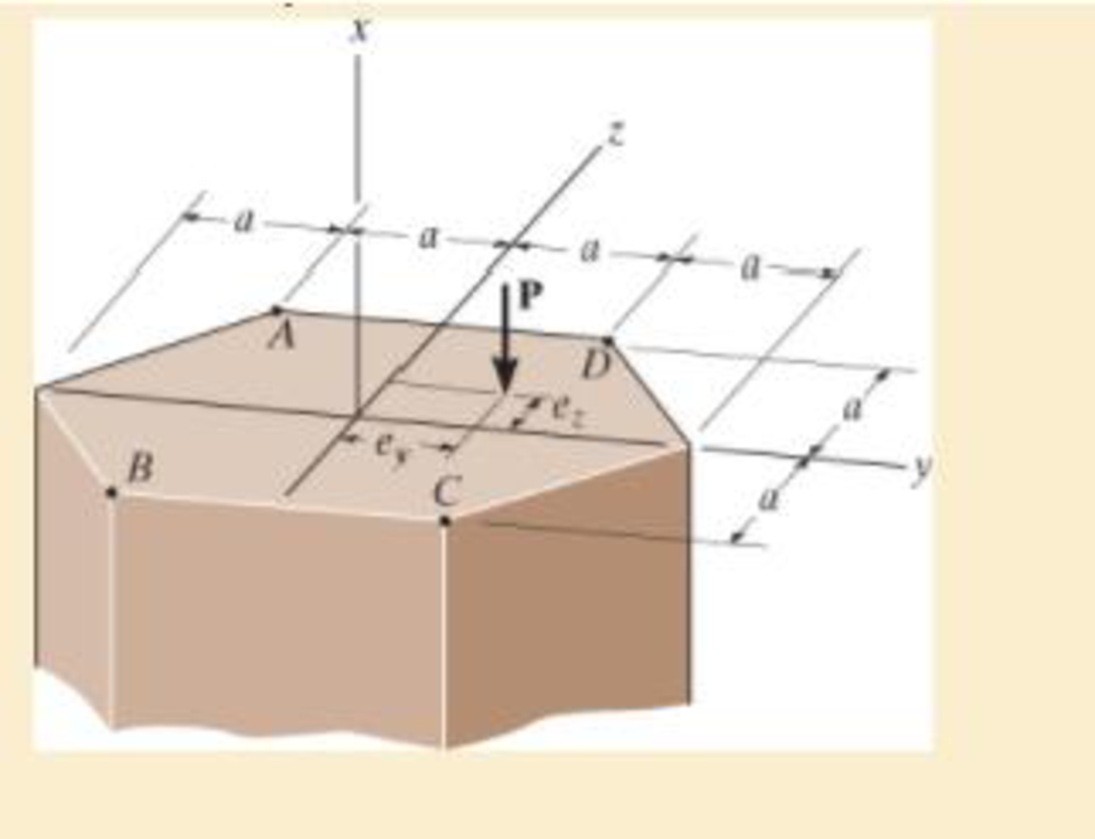
Chapter 8.2, Problem 8.51P
Specify the region to which this load can be applied without causing tensile stress at points A, B, C, and D.
Expert Solution & Answer
Want to see the full answer?
Check out a sample textbook solution
Students have asked these similar questions
3. The frame supports the distributed load shown. Determine the
state of stress acting at point E. (Note: frame picture shows the
locations of points E and D in the frame, cross-section picture
specifies the locations of these points in the cross-section.)
4 kN/m
-1.5 m+1.5 m
3 m
3 m
20 mm
60 mm
20 mm
5 m
D
50 mm
If the principal stresses are of opposite signs, then failure occurs in the plane. True or false?
Determine the tensile stress in a bar of 20 mm diameter when it is subjected to a pull of 450 N.
Chapter 8 Solutions
Mechanics of Materials, Student Value Edition (10th Edition)
Ch. 8.1 - If it is subjected to an internal pressure of p =...Ch. 8.1 - If it is subjected to an internal pressure of p =...Ch. 8.1 - The thin-walled cylinder can be supported in one...Ch. 8.1 - If the inner diameter of the tank is 22 in., and...Ch. 8.1 - Air pressure in the cylinder is increased by...Ch. 8.1 - Determine the maximum force P that can be exerted...Ch. 8.1 - A boiler is constructed of 8-mm-thick steel plates...Ch. 8.1 - 88. The steel water pipe has an inner diameter of...Ch. 8.1 - The steel water pipe has an inner diameter of 12...Ch. 8.1 - The A-36-steel band is 2 in. wide and is secured...
Ch. 8.1 - The gas pipe line is supported every 20 ft by...Ch. 8.1 - A pressure-vessel head is fabricated by welding...Ch. 8.1 - An A-36-steel hoop has an inner diameter of 23.99...Ch. 8.1 - The ring, having the dimensions shown, is placed...Ch. 8.1 - The inner ring A has an inner radius r1 and outer...Ch. 8.1 - Two hemispheres having an inner radius of 2 ft and...Ch. 8.1 - In order to increase the strength of the pressure...Ch. 8.2 - Show the results on the left segment.Ch. 8.2 - Show the stress that each of these loads produce...Ch. 8.2 - Fundamental Problems F81. Determine the normal...Ch. 8.2 - Show the results in a differential element at the...Ch. 8.2 - Determine the state of stress at point A on the...Ch. 8.2 - Determine the magnitude of the load P that will...Ch. 8.2 - Determine the state of stress at point B. Show the...Ch. 8.2 - Determine the state of stress at point A on the...Ch. 8.2 - Determine the state of stress at point A on the...Ch. 8.2 - Show the results in a differential element at the...Ch. 8.2 - Determine the shortest distance d to the edge of...Ch. 8.2 - The plate has a thickness of 20 mm and P acts...Ch. 8.2 - Plot the distribution of normal stress acting...Ch. 8.2 - Also, plot the normal-stress distribution over the...Ch. 8.2 - If the allowable normal stress for the steel is...Ch. 8.2 - If the applied force P = 1.50 kip, determine the...Ch. 8.2 - Determine the maximum normal stress on the cross...Ch. 8.2 - If the wood has an allowable normal stress of...Ch. 8.2 - Determine the maximum normal stress along section...Ch. 8.2 - Sketch the stress distribution along section aa of...Ch. 8.2 - Sketch the normal-stress distribution acting over...Ch. 8.2 - Determine the state of stress at points A and B,...Ch. 8.2 - If the force of 100 N is applied to the handles,...Ch. 8.2 - Determine the stress components at point A on the...Ch. 8.2 - Determine the stress components at point B on the...Ch. 8.2 - Determine the normal stress developed at points A...Ch. 8.2 - Sketch the normal-stress distribution acting over...Ch. 8.2 - Determine the state of stress at points A and B,...Ch. 8.2 - Determine the state of stress at point A on the...Ch. 8.2 - Determine the state of stress at point B on the...Ch. 8.2 - Determine the state of stress acting at point D....Ch. 8.2 - Determine the state of stress acting at point E....Ch. 8.2 - If it is subjected to the force system shown,...Ch. 8.2 - Solve Prob.840 for point B.Ch. 8.2 - Determine the stress components acting on the...Ch. 8.2 - Determine the stress components acting on the...Ch. 8.2 - Neglect the weight of the block.Ch. 8.2 - Neglect the weight of the block.Ch. 8.2 - He is supported uniformly by two bars, each having...Ch. 8.2 - Determine the state of stress at point A, and show...Ch. 8.2 - Determine the state of stress at point B, and show...Ch. 8.2 - Determine the state of stress at point C, and show...Ch. 8.2 - Determine the maximum radius e at which the load P...Ch. 8.2 - Specify the region to which this load can be...Ch. 8.2 - Determine the smallest force P that can be applied...Ch. 8.2 - The coiled spring is subjected to a force P. If we...Ch. 8.2 - The pins at C and D are at the same location as...Ch. 8.2 - Determine the state of stress at point A, and show...Ch. 8.2 - Determine the state of stress at point B, and show...Ch. 8.2 - Determine the stress components at points A and B...Ch. 8.2 - Determine the stress components at points C and D...Ch. 8.2 - Determine the stress components in the support...Ch. 8.2 - Determine the stress components in the support...Ch. 8.2 - If the force at the ram on the clamp at D is P= 8...Ch. 8.2 - Determine the maximum ram force P that can be...Ch. 8.2 - and an outer radius of 3.00 in. If the face of the...Ch. 8.2 - for points E and F.Ch. 8.2 - Determine the stress components at points A and B...Ch. 8.2 - Solve Prob.8-65 for points C and D.Ch. 8.2 - Due to internal gearing, this causes the block to...Ch. 8.2 - Determine the state of stress at point A and show...Ch. 8.2 - Solve Prob.868 for point B.Ch. 8.2 - Determine the stress components at point A. Sketch...Ch. 8.2 - for the stress components at point B.Ch. 8.2 - Determine the state of stress at point A at...Ch. 8.2 - Determine the state of stress at point B at...Ch. 8 - If it supports a cable loading of 800 lb,...Ch. 8 - Determine the state of stress at point E on the...Ch. 8 - Determine the state of stress at point F on the...Ch. 8 - The suspender arm AE has a square cross-sectional...Ch. 8 - If the cross section of the femur at section aa...Ch. 8 - If it has a mass of 5 kg/m, determine the largest...Ch. 8 - and is used to support the vertical reactions of...Ch. 8 - and is used to support the vertical reactions of...
Knowledge Booster


Learn more about
Need a deep-dive on the concept behind this application? Look no further. Learn more about this topic, mechanical-engineering and related others by exploring similar questions and additional content below.Similar questions
- If the A-36 solid steel rod has a diameter of 50 mm and has been loaded with loadings as shown in Figure Q4, determine the state of stress at point A and B and subsequently sketch their stress elements.arrow_forwardThe cross section of the rod in the picture is a circle with a diameter of 24 mm. The rod is pulled with a force of N = 20500 N, in addition to which a torque of T = 100 Nm acts. Determine the von Mises reference stress at point A on the outer surface of the rod. Note that it appears that the stress distributions caused by the normal force remain constant over the entire length of the beam! A plane stress state can be assumed at the point under consideration. Use units [N, mm] for calculations Please enter an answer to one decimal place. Do not round off the invoices in the intermediate stages, but only the final answer!arrow_forwardThe cross section of the rod in the picture is a circle with a diameter of 24 mm. The rod is pulled with a force of N = 20500 N, in addition to which a torque of T = 100 Nm acts. Determine the von Mises reference stress at point A on the outer surface of the rod. Note that it appears that the stress distributions caused by the normal force remain constant over the entire length of the beam! A plane stress state can be assumed at the point under consideration. Use units [N, mm] for calculations Please enter an answer to one decimal place. Do not round off the invoices in the intermediate stages, but only the final answer! The dimensions are: Boat mass mv = 1018 kg Dimension L1 = 3565 mm Dimension L2 = 5221 mm Dimension L3 = 6654 mm Dimension L4 = 1500 mm Dimension L5 = 600 mmarrow_forward
- 2. The bar AC is supported by a pin at A and a cable that runs from B to E around the frictionless pully at D. If the allowable tensile stress oallow = 5.2 ksi for the cable, determine the required minimum diameter (inch) of the cable. The cylinder (connected at C) weighs 890 lb. Neglect weight and thickness of the bar AC. D 4 3 A C 5 ft 5 ft -4 ft 890 lbarrow_forward3- The modulus of elasticity, and the modulus of resilience. 4- The final or fracture strain of a steel specimen, if you know that the final length of specimen after testing is 58.5mm. 5- The true stress and strain for ultimate point. Q3: The yoke-and-rod connection is subjected to a tensile force of 15 kN. Determine the average normal stress in each rod and the average shear stress in the pin A between the members. Finally, find the shear strain in pin A. Take G steel= 75GPA 40 mm 15 kN. 30 mm 30 mm 15 kN 04: In figure as shown below, assume that a 35mm diameter rivet joint the plates which are each 150mm wide. (a) if the allowable stresses 200 MPa for bearing in the plate material and 120 MPa for shearing of the rivet, determine the minimum thickness of each plate. (b)Under the conditions specified in part (a) what is the largest average stress in the plate. 35mmarrow_forwardDetermine the state of stress acting at point D. Take P₁ = 120 kN and P₂ = 45 kN. (Figure 1) Figure L -1.5m- +1.5m-1.5 m- 0.5 m 40 mm 100 mm 60 mm 80 mm 1 of 1 > Find op- Express your answer to three significant figures and include the appropriate units. Enter negative value in the case of compression and positive value in the case of tension. od= - 154.88 Submit Part B Previous Answers Request Answer X Incorrect; Try Again; 3 attempts remaining MPa Find TD- Express your answer to three significant figures and include the appropriate units. JA TD= Value Units ?arrow_forward
- Problem 3-2. For the following section, determine the stresses at points A, B, C, D, E and F. Given: M = 14 kN.m N A M FL E B 60 mm 60 mm C D 60 mm 60 mm 60 mm*60 mmarrow_forwardThe screw of the clamp exerts a compressive force of 500 lb on the woodblocks. Sketch the stress distribution along section a–a of the clamp. The cross section is rectangular, 0.75 in. by 0.50 in.arrow_forwardProblem 2: The state of stress for a machine element is shown below. Using the Maximum Shear Stress Theory, determine the minimum required yield strength of the part. 10 ksi 4 ksi 8 ksiarrow_forward
- Please answer this NEATLY, COMPLETELY, and CORRECTLY for an UPVOTE. Draw appropriate FBDs showing how the internal forces were determined. A square bar (side length = 50 mm) is welded to a fixed supporting slab. A 30-mm diameter pin is inserted in the bar. When the loading shown is applied, determine the following: a. maximum normal stress in the bar (MPa) and bearing stress between the pin and the bar (MPa)b. stress in the weld between the bar and the supporting slab (MPa)c. shear stress in the pin (MPa) and shear stress in the bar (MPa)arrow_forwardThe supporting wheel on a scaffold is held in place on the leg using a 4-mm-diameter pin as shown. (Figure 1) Figure 1 of 1 > Part A If the wheel is subjected to a normal force of P = 3.3 kN, determine the average shear stress developed in the pin. Neglect friction between the inner scaffold puller leg and the tube used on the wheel. Express your answer to three significant figures and include the appropriate units. Tavg= Submit Provide Feedback Value A Request Answer C Units ? Next >arrow_forwardThe element in the image has a horizontal force of 20 N and a vertical force of 25 N. The element was made of a 25.4 mm diameter steel bar. Determine:to. The four states of stress from the farthest place of the forces and obtain the critical point.b. For the critical point, construct the Mohr circle.C. Obtain the maximum principal and normal shear stresses for the critical point.d. The angles at which the maximum normal and shear stresses occur.and. Draw the rotated tension state for the angles obtained and with the corresponding tensions.arrow_forward
arrow_back_ios
SEE MORE QUESTIONS
arrow_forward_ios
Recommended textbooks for you
 Elements Of ElectromagneticsMechanical EngineeringISBN:9780190698614Author:Sadiku, Matthew N. O.Publisher:Oxford University Press
 Mechanics of Materials (10th Edition)Mechanical EngineeringISBN:9780134319650Author:Russell C. HibbelerPublisher:PEARSON
 Thermodynamics: An Engineering ApproachMechanical EngineeringISBN:9781259822674Author:Yunus A. Cengel Dr., Michael A. BolesPublisher:McGraw-Hill Education
 Control Systems EngineeringMechanical EngineeringISBN:9781118170519Author:Norman S. NisePublisher:WILEY
 Mechanics of Materials (MindTap Course List)Mechanical EngineeringISBN:9781337093347Author:Barry J. Goodno, James M. GerePublisher:Cengage Learning
 Engineering Mechanics: StaticsMechanical EngineeringISBN:9781118807330Author:James L. Meriam, L. G. Kraige, J. N. BoltonPublisher:WILEY
Elements Of Electromagnetics
Mechanical Engineering
ISBN:9780190698614
Author:Sadiku, Matthew N. O.
Publisher:Oxford University Press
Mechanics of Materials (10th Edition)
Mechanical Engineering
ISBN:9780134319650
Author:Russell C. Hibbeler
Publisher:PEARSON
Thermodynamics: An Engineering Approach
Mechanical Engineering
ISBN:9781259822674
Author:Yunus A. Cengel Dr., Michael A. Boles
Publisher:McGraw-Hill Education
Control Systems Engineering
Mechanical Engineering
ISBN:9781118170519
Author:Norman S. Nise
Publisher:WILEY
Mechanics of Materials (MindTap Course List)
Mechanical Engineering
ISBN:9781337093347
Author:Barry J. Goodno, James M. Gere
Publisher:Cengage Learning
Engineering Mechanics: Statics
Mechanical Engineering
ISBN:9781118807330
Author:James L. Meriam, L. G. Kraige, J. N. Bolton
Publisher:WILEY
EVERYTHING on Axial Loading Normal Stress in 10 MINUTES - Mechanics of Materials; Author: Less Boring Lectures;https://www.youtube.com/watch?v=jQ-fNqZWrNg;License: Standard YouTube License, CC-BY