
Statics and Mechanics of Materials Plus Mastering Engineering with Pearson eText - Access Card Package (5th Edition)
5th Edition
ISBN: 9780134301006
Author: Russell C. Hibbeler
Publisher: PEARSON
expand_more
expand_more
format_list_bulleted
Videos
Textbook Question
Chapter 8.4, Problem 7P
The rigid beam is supported by a pin at C and an A-36 steel guy wire AB. If the wire has a diameter of 0.2 in., determine how much it stretches when a distributed load of w = 100 lb/ft acts on the beam. The material remains elastic.
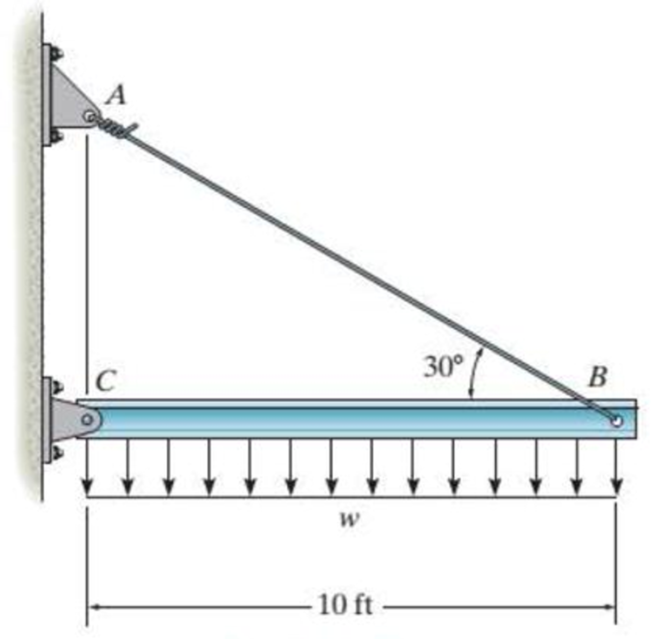
Probs. 8-7/8
Expert Solution & Answer
Want to see the full answer?
Check out a sample textbook solution
Students have asked these similar questions
The rigid beam is supported by three 25-mm diameter A-36 steel rods. If the beam supports the force of
P=230 kN, determine the force developed in each rod. Consider the steel to be an elastic perfectly
plastic material.
Detailed solution
*R8-4. The wires each have a diameter of 12 mm, length
of 0.6 m, and are made from 304 stainless steel. If P-30 kN,
determine the angle of tilt of the rigid beam AB.
De
0.6 m
-0.6 m-
-0.3 m-
The strut is supported by a pin at C and an A-36 steel guy wire AB. If the wire has a diameter of 1,2 m , determine how much it stretches when the distributed load acts on the strut.
Chapter 8 Solutions
Statics and Mechanics of Materials Plus Mastering Engineering with Pearson eText - Access Card Package (5th Edition)
Ch. 8.4 - Define a homogeneous material.Ch. 8.4 - Prob. 2FPCh. 8.4 - Prob. 3FPCh. 8.4 - Prob. 4FPCh. 8.4 - Prob. 5FPCh. 8.4 - As the temperature increases the modulus of...Ch. 8.4 - Prob. 7FPCh. 8.4 - Prob. 8FPCh. 8.4 - Prob. 9FPCh. 8.4 - Prob. 10FP
Ch. 8.4 - The material for the 50-mm-long specimen has the...Ch. 8.4 - If the elongation of wire BC is 0.2 mm after the...Ch. 8.4 - A tension test was performed on a steel specimen...Ch. 8.4 - Data taken from a stressstrain test for a ceramic...Ch. 8.4 - Data taken from a stressstrain test for a ceramic...Ch. 8.4 - Prob. 4PCh. 8.4 - The stress-strain diagram for a steel alloy having...Ch. 8.4 - Prob. 6PCh. 8.4 - The rigid beam is supported by a pin at C and an...Ch. 8.4 - The rigid beam is supported by a pin at C and an...Ch. 8.4 - Prob. 9PCh. 8.4 - The stressstrain diagram for an aluminum alloy...Ch. 8.4 - The stressstrain diagram for an aluminum alloy...Ch. 8.4 - Prob. 12PCh. 8.4 - A bar having a length of 5 in. and cross-sectional...Ch. 8.4 - The rigid pipe is supported by a pin at A and an...Ch. 8.4 - The rigid pipe is supported by a pin at A and an...Ch. 8.4 - Prob. 16PCh. 8.4 - The rigid beam is supported by a pin at C and an...Ch. 8.4 - Prob. 18PCh. 8.4 - Prob. 19PCh. 8.6 - A 100 mm long rod has a diameter of 15 mm. If an...Ch. 8.6 - A solid circular rod that is 600 mm long and 20 mm...Ch. 8.6 - Prob. 15FPCh. 8.6 - Prob. 16FPCh. 8.6 - The acrylic plastic rod is 200 mm long and 15 mm...Ch. 8.6 - The plug has a diameter of 30 mm and fits within a...Ch. 8.6 - The elastic portion of the stress-strain diagram...Ch. 8.6 - The elastic portion of the stress-strain diagram...Ch. 8.6 - The brake pads for a bicycle tire arc made of...Ch. 8.6 - The lap joint is connected together using a 1.25...Ch. 8.6 - The lap joint is connected together using a 1.25...Ch. 8.6 - Prob. 27PCh. 8.6 - The shear stress-strain diagram for an alloy is...Ch. 8.6 - Prob. 29PCh. 8 - The elastic portion of the tension stress-strain...Ch. 8 - Prob. 2RPCh. 8 - Prob. 3RPCh. 8 - Prob. 4RPCh. 8 - Prob. 5RPCh. 8 - Prob. 6RPCh. 8 - The stress-strain diagram for polyethylene, which...Ch. 8 - The pipe with two rigid caps attached to its ends...Ch. 8 - Prob. 9RPCh. 8 - Prob. 10RP
Knowledge Booster


Learn more about
Need a deep-dive on the concept behind this application? Look no further. Learn more about this topic, mechanical-engineering and related others by exploring similar questions and additional content below.Similar questions
- explain how to find the resultant internal loading acting on the cross section at point A. Draw all necessary free-body diagrams, and indicate the relevant equations of equilibrium. Do not calculate values The lettered dimensions, angles, and loads are assumed to be known. P7-1.arrow_forwardThe pole is supported by a pin at B and A-36 steel guy wire AC. If the wire has a diameter of 0.2. Modulus of Elasticity of Steel = 200GPA or 29x103 ksi Poisson's ratio of steel=0.321 a. Determine how much the wire stretches when the horizontal force acts on the pole. 3 ft 30 D 2.5 kip 4 ft B b. Determine the change in the wire's radius c. At what angle is the principal stresses on pole BC? Use Mohr's Circle. d. What is the principal stress in pol BC? Use Mohr's Circle e. Draw the stresses on a unit element acting on 35-degree clockwise direction of pole BC. Use Mohr's Circle. f. What are the principal stresses in point D? Use Mohr's Circle. (answer in ksi) g. At what angle is the principal stresses acting on point D? Use Mohr 's Circle. h. Draw the stresses on a unit element acting on 35degree-clockwise direction of point D. Use Mohr's Circle. (answer in ksi)arrow_forwardThe rigid beam is supported by three 25-mm diameter A-36 steel rods. If the beam supports the force of P=230 kN, determine the force developed in each rod. Consider the steel to be an elastic perfectly plastic material. Complete solution if possible.arrow_forward
- The rigid beam is supported by three 25-mm diameter A-36 steel rods. If the beam supports the force of P=230 kN, determine the force developed in each rod. Consider the steel to be an elastic perfectly plastic material.arrow_forward9-15. The steel bar has the original dimensions shown in the figure. If it is subjected to an axial load of 50 kN. determine the change in its length and its new cross-sectional dimensions at section aa. E-200 GPa,-029. 50 AN SOLN -20 mm mm s50 mm 50 mm 50 kN 200 mmarrow_forwardThe column is constructed from high-strength concrete and four A-36 steel reinforcing rods. If it is subjected to an axial force of 800 kN, determine the required diameter of each rod (mm) so that one-fourth of the load is carried by the steel and three-fourths by the concrete. Est = 200 GPa, Ec = 25 GPa.arrow_forward
- explain how to find the resultant internal loading acting on the cross section at point A. Draw all necessary free-body diagrams and indicate the relevant equations of equilibrium. Do not calculate values The lettered dimensions, angles, and loads are assumed to be known. P7-1. м в -a/2--/2-arrow_forwardThe bent bar is supported by smooth journal bearings at A, B and C and is subjected to couple moment of 200 N.m. Determine the support reaction at each of the smooth journal bearings. 200 N.m /0.4 m/ B 0.7 m 0.6 m Figure 2arrow_forward7-26. The beam is made from three boards glued together at the seams A and B. If it is subjected to the loading shown, determine the maximum vertical shear force resisted by the top flange of the beam. The supports at C and D exert only vertical reactions on the beam. 5 kip 5 kip 5 kip D - 4 ft 3 ft 1.5 ft 1.5 ft 4 ft 6 in. 1.5 in. 8 in. 2 in. B. 1.5 in. Tarrow_forward
- *3-8. The strut is supported by a pin at C and an A-36 steel guy wire AB. If the wire has 'a diameter of 5 mm, determine how much it stretches when the distributed load acts on the strut. 60 3.4 kN/m 2.7 marrow_forwardThe rigid beam is supported by a pin at C and an A-36 steel guy wire AB. 30 10 ft Part A If the wire has a diameter of 0.5 in., determine how much it stretches when a distributed load of 190 lb/ft acts on the beam. The material remains elastic. Express your answer to three significant figures and include appropriate units. µA ? SAB = 0.02668 inarrow_forwardexplain how to find the resultant internal loading acting on the cross section at point A. Draw all necessary free-body diagrams, and indicate the relevant equations of equilibrium. Do not calculate values The lettered dimensions, angles, and loads are assumed to be known. P7-1. вarrow_forward
arrow_back_ios
SEE MORE QUESTIONS
arrow_forward_ios
Recommended textbooks for you
 Elements Of ElectromagneticsMechanical EngineeringISBN:9780190698614Author:Sadiku, Matthew N. O.Publisher:Oxford University Press
 Mechanics of Materials (10th Edition)Mechanical EngineeringISBN:9780134319650Author:Russell C. HibbelerPublisher:PEARSON
 Thermodynamics: An Engineering ApproachMechanical EngineeringISBN:9781259822674Author:Yunus A. Cengel Dr., Michael A. BolesPublisher:McGraw-Hill Education
 Control Systems EngineeringMechanical EngineeringISBN:9781118170519Author:Norman S. NisePublisher:WILEY
 Mechanics of Materials (MindTap Course List)Mechanical EngineeringISBN:9781337093347Author:Barry J. Goodno, James M. GerePublisher:Cengage Learning
 Engineering Mechanics: StaticsMechanical EngineeringISBN:9781118807330Author:James L. Meriam, L. G. Kraige, J. N. BoltonPublisher:WILEY
Elements Of Electromagnetics
Mechanical Engineering
ISBN:9780190698614
Author:Sadiku, Matthew N. O.
Publisher:Oxford University Press
Mechanics of Materials (10th Edition)
Mechanical Engineering
ISBN:9780134319650
Author:Russell C. Hibbeler
Publisher:PEARSON
Thermodynamics: An Engineering Approach
Mechanical Engineering
ISBN:9781259822674
Author:Yunus A. Cengel Dr., Michael A. Boles
Publisher:McGraw-Hill Education
Control Systems Engineering
Mechanical Engineering
ISBN:9781118170519
Author:Norman S. Nise
Publisher:WILEY
Mechanics of Materials (MindTap Course List)
Mechanical Engineering
ISBN:9781337093347
Author:Barry J. Goodno, James M. Gere
Publisher:Cengage Learning
Engineering Mechanics: Statics
Mechanical Engineering
ISBN:9781118807330
Author:James L. Meriam, L. G. Kraige, J. N. Bolton
Publisher:WILEY
Mechanics of Materials Lecture: Beam Design; Author: UWMC Engineering;https://www.youtube.com/watch?v=-wVs5pvQPm4;License: Standard Youtube License