Connect 2 Semester Access Card for Vector Mechanics for Engineers: Statics and Dynamics
11th Edition
ISBN: 9780077687298
Author: Ferdinand P. Beer, E. Russell Johnston Jr., David Mazurek, Phillip J. Cornwell
Publisher: McGraw-Hill Education
expand_more
expand_more
format_list_bulleted
Concept explainers
Videos
Textbook Question
Chapter 8.4, Problem 8.133P
Solve Prob. 8.113 assuming that the flat belt and pulleys are replaced by a V belt and V pulleys with α = 36°. (The angle α is as shown in Fig. 8.15a.)
8.113 A flat belt is used to transmit a couple from pulley A to pulley B. The radius of each pulley is 60 mm, and a force of magnitude P = 900 N is applied as shown to the axle of pulley A. Knowing that the coefficient of static friction is 0.35, determine (a) the largest couple that can be transmitted, (b) the corresponding maximum value of the tension in the belt.
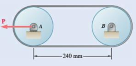
Fig. P8.113
Expert Solution & Answer
Want to see the full answer?
Check out a sample textbook solution
Students have asked these similar questions
In the planetary gear system shown, the radius of the central gear A is a= 18 mm, the radius of each planetary gear is b , and the radius of the outer gear E is (a + 2b). A clockwise couple with a magnitude of MA = 10 N.m is applied to the central gear A and a counterclockwise couple with a magnitude of MS= 50 N.m is applied to the spider BCD . If the system is to be in equilibrium, determine (a) the required radius b of the planetary gears, (b) the magnitude ME of the couple that must be applied to the outer gear E.
Solve Prob. 4.91, assuming that the pulley rotates at a constant rate and that TB = 104 N, T'B = 84 N, and TC= 175 N.(Reference to Problem 4.91):Two transmission belts pass over a double-sheaved pulley that is attached to an axle supported by bearings at A and D . The radius of the inner sheave is 125 mm and the radius of the outer sheave is 250 mm. Knowing that when the system is at rest, the tension is 90 N in both portions of belt B and 150 N in both portions of belt C, determine the reactions at A and D . Assume that the bearing at D does not exert any axial thrust.
y
150 mm 100 mm
TB
200 mm
D
Tc
T'c
PROBLEM 4.91
Two transmission belts pass over a double-
sheaved pulley that is attached to an axe
supported by bearings at A and D. The radius of
the inner sheave is 125 mm and the radius
of the outer sheave is 250 mm. Knowing that
when the system is at rest, the tension is 90 N in
both portions of belt B and 150 N in both
portions of belt C, determine the reactions at A
and D. Assume that the bearing at D does
not exert any axial thrust.
Chapter 8 Solutions
Connect 2 Semester Access Card for Vector Mechanics for Engineers: Statics and Dynamics
Ch. 8.1 - Knowing that the coefficient of friction between...Ch. 8.1 - Two blocks A and B are connected by a cable as...Ch. 8.1 - A cord is attached to and partially wound around a...Ch. 8.1 - A 40-kg packing crate must be moved to the left...Ch. 8.1 - Prob. 8.1PCh. 8.1 - Prob. 8.2PCh. 8.1 - Prob. 8.3PCh. 8.1 - Prob. 8.4PCh. 8.1 - Prob. 8.5PCh. 8.1 - The 20-lb block A hangs from a cable as shown....
Ch. 8.1 - The 10-kg block is attached to link AB and rests...Ch. 8.1 - Considering only values of less than 90,...Ch. 8.1 - Prob. 8.9PCh. 8.1 - Prob. 8.10PCh. 8.1 - The 50-lb block A and the 25-lb block B are...Ch. 8.1 - The 50-lb block A and the 25-lb block B are...Ch. 8.1 - Three 4-kg packages A, B, and C are placed on a...Ch. 8.1 - Prob. 8.14PCh. 8.1 - A uniform crate with a mass of 30 kg must be moved...Ch. 8.1 - A worker slowly moves a 50-kg crate to the left...Ch. 8.1 - Prob. 8.17PCh. 8.1 - Prob. 8.18PCh. 8.1 - Prob. 8.19PCh. 8.1 - Prob. 8.20PCh. 8.1 - Prob. 8.21PCh. 8.1 - Prob. 8.22PCh. 8.1 - Prob. 8.23PCh. 8.1 - Prob. 8.24PCh. 8.1 - Prob. 8.25PCh. 8.1 - Prob. 8.26PCh. 8.1 - The press shown is used to emboss a small seal at...Ch. 8.1 - The machine base shown has a mass of 75 kg and is...Ch. 8.1 - Prob. 8.29PCh. 8.1 - Prob. 8.30PCh. 8.1 - Prob. 8.31PCh. 8.1 - Prob. 8.32PCh. 8.1 - Prob. 8.33PCh. 8.1 - Prob. 8.34PCh. 8.1 - Prob. 8.35PCh. 8.1 - Prob. 8.36PCh. 8.1 - A 1.2-m plank with a mass of 3 kg rests on two...Ch. 8.1 - Two identical uniform boards, each with a weight...Ch. 8.1 - Prob. 8.39PCh. 8.1 - Prob. 8.40PCh. 8.1 - A 10-ft beam, weighing 1200 lb, is to be moved to...Ch. 8.1 - (a) Show that the beam of Prob. 8.41 cannot be...Ch. 8.1 - Two 8-kg blocks A and B resting on shelves are...Ch. 8.1 - Prob. 8.44PCh. 8.1 - Prob. 8.45PCh. 8.1 - Two slender rods of negligible weight are...Ch. 8.1 - Two slender rods of negligible weight are...Ch. 8.2 - The machine part ABC is supported by a...Ch. 8.2 - Prob. 8.49PCh. 8.2 - Prob. 8.50PCh. 8.2 - Prob. 8.51PCh. 8.2 - Prob. 8.52PCh. 8.2 - Solve Prob. 8.52 assuming that the end of the beam...Ch. 8.2 - Prob. 8.54PCh. 8.2 - Prob. 8.55PCh. 8.2 - Block A supports a pipe column and rests as shown...Ch. 8.2 - Prob. 8.57PCh. 8.2 - Prob. 8.58PCh. 8.2 - Prob. 8.59PCh. 8.2 - Prob. 8.60PCh. 8.2 - Prob. 8.61PCh. 8.2 - Prob. 8.62PCh. 8.2 - Prob. 8.63PCh. 8.2 - A 15 wedge is forced under a 50-kg pipe as shown....Ch. 8.2 - A 15 wedge is forced under a 50-kg pipe as shown....Ch. 8.2 - Prob. 8.66PCh. 8.2 - Prob. 8.67PCh. 8.2 - Prob. 8.68PCh. 8.2 - Prob. 8.69PCh. 8.2 - Prob. 8.70PCh. 8.2 - Prob. 8.71PCh. 8.2 - The position of the automobile jack shown is...Ch. 8.2 - Prob. 8.73PCh. 8.2 - Prob. 8.74PCh. 8.2 - Prob. 8.75PCh. 8.2 - Prob. 8.76PCh. 8.3 - A lever of negligible weight is loosely fitted...Ch. 8.3 - Prob. 8.78PCh. 8.3 - 8.79 and 8.80 The double pulley shown is attached...Ch. 8.3 - Prob. 8.80PCh. 8.3 - 8.81 and 8.82 The double pulley shown is attached...Ch. 8.3 - Prob. 8.82PCh. 8.3 - Prob. 8.83PCh. 8.3 - The block and tackle shown are used to lower a...Ch. 8.3 - Prob. 8.85PCh. 8.3 - Prob. 8.86PCh. 8.3 - Prob. 8.87PCh. 8.3 - 8.87 and 8.88 A lever AB of negligible weight is...Ch. 8.3 - Prob. 8.89PCh. 8.3 - Prob. 8.90PCh. 8.3 - Prob. 8.91PCh. 8.3 - 8.92 Knowing that a couple of magnitude 30 N·m is...Ch. 8.3 - Prob. 8.93PCh. 8.3 - Prob. 8.94PCh. 8.3 - Prob. 8.95PCh. 8.3 - Prob. 8.96PCh. 8.3 - Solve Prob. 8.93 assuming that the normal force...Ch. 8.3 - Prob. 8.98PCh. 8.3 - Prob. 8.99PCh. 8.3 - A 900-kg machine base is rolled along a concrete...Ch. 8.3 - Prob. 8.101PCh. 8.3 - Prob. 8.102PCh. 8.4 - A rope having a weight per unit length of 0.4...Ch. 8.4 - Prob. 8.104PCh. 8.4 - Two cylinders are connected by a rope that passes...Ch. 8.4 - Prob. 8.106PCh. 8.4 - Prob. 8.107PCh. 8.4 - Prob. 8.108PCh. 8.4 - A band belt is used to control the speed of a...Ch. 8.4 - Prob. 8.110PCh. 8.4 - The setup shown is used to measure the output of a...Ch. 8.4 - A flat belt is used to transmit a couple from drum...Ch. 8.4 - Prob. 8.113PCh. 8.4 - 8.114 Solve Prob. 8.113 assuming that the belt is...Ch. 8.4 - The speed of the brake drum shown is controlled by...Ch. 8.4 - The speed of the brake drum shown is controlled by...Ch. 8.4 - Prob. 8.117PCh. 8.4 - Bucket A and block C are connected by a cable that...Ch. 8.4 - Prob. 8.119PCh. 8.4 - Prob. 8.120PCh. 8.4 - 8.121 and 8.123 A cable is placed around three...Ch. 8.4 - Prob. 8.122PCh. 8.4 - Prob. 8.123PCh. 8.4 - Prob. 8.124PCh. 8.4 - Prob. 8.125PCh. 8.4 - Prob. 8.126PCh. 8.4 - Prob. 8.127PCh. 8.4 - The 10-lb bar AE is suspended by a cable that...Ch. 8.4 - Prob. 8.129PCh. 8.4 - Prove that Eqs. (8.13) and (8.14) are valid for...Ch. 8.4 - Complete the derivation of Eq. (8.15), which...Ch. 8.4 - Prob. 8.132PCh. 8.4 - Solve Prob. 8.113 assuming that the flat belt and...Ch. 8 - 8.134 and 8.135 The coefficients of friction are S...Ch. 8 - Prob. 8.135RPCh. 8 - Prob. 8.136RPCh. 8 - A slender rod with a length of L is lodged between...Ch. 8 - The hydraulic cylinder shown exerts a force of 3...Ch. 8 - Prob. 8.139RPCh. 8 - Bar AB is attached to collars that can slide on...Ch. 8 - Two 10 wedges of negligible weight are used to...Ch. 8 - A 10 wedge is used to split a section of a log....Ch. 8 - Prob. 8.143RPCh. 8 - A lever of negligible weight is loosely fitted...Ch. 8 - In the pivoted motor mount shown, the weight W of...
Knowledge Booster


Learn more about
Need a deep-dive on the concept behind this application? Look no further. Learn more about this topic, mechanical-engineering and related others by exploring similar questions and additional content below.Similar questions
- Q.1 For the instant of the Proell governor mechanism shown below, the tension in the lower link will be [weight of ball is 30 N and weight of sleeve is 80 N] N. 240 mm 208 mm A Carrow_forwardFor the given loads w = 28 KN/m and M=70 KN.m is supported as shown by a roller at D and a hinge at D W kN/m M kN - m 1m- 3 m- 2 m Magnitude of reaction at D is (KN) а. 56 b. 140 c. 112 d. 168 e. 196 Magnitude of reaction at A is (KN) а. 126 b. 168 c. 112 d. 56 е. 28 Shear force just to the right of D Shear force just to the left of D Bending moment just to the right of B (KN.m) a. -28 b. -42 C. -56 d. -70 e. -84 Maximum absolute value of bending moment (KN.m) isarrow_forwardThe pipe ABCDE is supported by ball-and-socket joints at A and D and by cable ECF that passes through a ring C with negligible friction and is attached to hooks at E and F. Knowing that the frame supports a uniformly distributed load of 1500 N/m along segment AB, do the following.1) Shows the correct vector representation of the resultant of the two tension forces acting at ring C. Note that T_CF = T_CE = T2) Explain along which line/axis you can sum moments to generate an equilibrium equation with only the magnitude of the tension force as the unknown. Explain your choice.3) Find the magnitude of the tension force.arrow_forward
- Two rods are connected by a slider block as shown. Given: MB= 250 lb-in. MA MB 25° 15 in. A |B 15 in.- Draw the free-body diagram needed to determine the couple MA required to hold the system in equilibrium.arrow_forward3 1 kN 4 esc 2 kN Во C 2 kN Do 1 E 180 mm 1 kN F G 2m 2m 2m 2m 2m 2m 160 mm B H C K A 90 mm 0 m 1 m 1m 1m L 1m 240 N 31 PROBLEM 6.131 Arm ABC is connected by pins to a collar at B and to crank CD at C. Neglecting the effect of friction, determine the couple M required to hold the system in equilibrium when 0=0. ▸ % PROBLEM 6.21 L Determine the force in each of the members located to the left of FG for the scissors roof truss shown. State whether each member is in tension or compression. A 6 & 7 * 8 of J O Jul 17 8:13 xarrow_forwardA freight wagon is at rest on a track at an angle of 25o to the vertical. The gross weight of the wagon and its load is 36kN and acts at a point 750 mm from the track, in the middle between the two axles. The wagon is held by a cable 600 mm from the track. Determine the traction on the cable and the reaction on each pair of wheels.arrow_forward
- The frictional resistance of a thrust bearing decreases as the shaft and bearing surfaces wear out. It is generally assumed that the wear is directly proportional to the distance traveled by any given point of the shaft and thus to the distance r from the point to the axis of the shaft. Assuming then that the normal force per unit area is inversely proportional to r , show that the magnitude M of the couple required to overcome the frictional resistance of a worn-out end bearing (with contact over the full circular area) is equal to 75 percent of the value given by Eq. (8.9) for a new bearing.arrow_forwardThe 10-lb bar AE is suspended by a cable that passes over a 5-in.-radius drum. Vertical motion of end E of the bar is prevented by the two stops shown. Knowing that μs= 0.30 between the cable and the drum, determine (a) the largest counterclockwise couple M0 that can be applied to the drum if slipping is not to occur, (b) the corresponding force exerted on end E of the bar.arrow_forwardThree cylinders are piled in a rectangular ditch as shown, neglecting friction. Wa=15lb, Wb=40lb and Wc=20lb. Determine reaction between cylinder A and the floor, reaction between cylinder A and wall, reaction between cylinder A and cylinder B, reaction between cylinder B and cylinder C, reaction between cylinder B and the wall, and reaction between cylinder C and the wall.arrow_forward
- Required information Problem 06.123 - Toggle vise - DEPENDENT MULTI-PART PROBLEM - ASSIGN ALL PARTS NOTE: This is a multi-part question. Once an answer is submitted, you will be unable to return to this part. A 260-lb force P directed vertically downward is applied to the toggle vise at C. Also, link BD is 6 in. long and take a = 4 in. P B 15° 6 in. Problem 06.123.b - Toggle vise DE Determine the horizontal force exerted on block E. The horizontal force exerted on block Eis lb. →arrow_forwardExercises: 1. The box wrench in Fig. 99 is used to tighten the bolt at A. If the wrench does not turn when the load is applied to the handle, determine the torque or moment applied to the bolt and the force of the wrench on the bolt. 300 mm 400 mm 60° 12 52'N 30 N Fig. 99 2. Determine the horizontal and vertical 750 lb components of reaction on the member at the pin A, and the normal reaction at the roller B in Fig. 100. 3 ft 3 ft 2 ft 30 Fig. 100 3. The uniform smooth rod shown in Fig. 101 is subjected to a force and couple moment. If the rod is supported at A by a smooth wall and at B and C either at the top or bottom by rollers, determine the reactions at these supports. Neglect the weight of the rod. 2 m 4 m 4000 N m 2m B 300 N 2 m 30° Fig. 101 4. Determine the support reactions on the member in Fig. 102. The collar at A is fixed to the member and can slide vertically along the vertical shaft. 900 N 1.5 m- 1.5 m 1 m 45° 500 N marrow_forwardThe L-shaped member ACB is supported by a pin and bracket at C and by an inextensible cord attached at A and B and passing over a frictionless pulley at D. The tension may be assumed to be the same in portions AD and BD of the cord. If the magnitudes of the forces applied at A and B are, respectively, P = 25 lb and Q = 0, determine (a) the tension in the cord, (b) the reaction at Carrow_forward
arrow_back_ios
SEE MORE QUESTIONS
arrow_forward_ios
Recommended textbooks for you
 Elements Of ElectromagneticsMechanical EngineeringISBN:9780190698614Author:Sadiku, Matthew N. O.Publisher:Oxford University Press
 Mechanics of Materials (10th Edition)Mechanical EngineeringISBN:9780134319650Author:Russell C. HibbelerPublisher:PEARSON
 Thermodynamics: An Engineering ApproachMechanical EngineeringISBN:9781259822674Author:Yunus A. Cengel Dr., Michael A. BolesPublisher:McGraw-Hill Education
 Control Systems EngineeringMechanical EngineeringISBN:9781118170519Author:Norman S. NisePublisher:WILEY
 Mechanics of Materials (MindTap Course List)Mechanical EngineeringISBN:9781337093347Author:Barry J. Goodno, James M. GerePublisher:Cengage Learning
 Engineering Mechanics: StaticsMechanical EngineeringISBN:9781118807330Author:James L. Meriam, L. G. Kraige, J. N. BoltonPublisher:WILEY
Elements Of Electromagnetics
Mechanical Engineering
ISBN:9780190698614
Author:Sadiku, Matthew N. O.
Publisher:Oxford University Press
Mechanics of Materials (10th Edition)
Mechanical Engineering
ISBN:9780134319650
Author:Russell C. Hibbeler
Publisher:PEARSON
Thermodynamics: An Engineering Approach
Mechanical Engineering
ISBN:9781259822674
Author:Yunus A. Cengel Dr., Michael A. Boles
Publisher:McGraw-Hill Education
Control Systems Engineering
Mechanical Engineering
ISBN:9781118170519
Author:Norman S. Nise
Publisher:WILEY
Mechanics of Materials (MindTap Course List)
Mechanical Engineering
ISBN:9781337093347
Author:Barry J. Goodno, James M. Gere
Publisher:Cengage Learning
Engineering Mechanics: Statics
Mechanical Engineering
ISBN:9781118807330
Author:James L. Meriam, L. G. Kraige, J. N. Bolton
Publisher:WILEY
Power Transmission; Author: Terry Brown Mechanical Engineering;https://www.youtube.com/watch?v=YVm4LNVp1vA;License: Standard Youtube License