
Videos
a)
The rate of exergy destroyed during the process and the exit temperature
a)
Answer to Problem 64P
The rate of exergy destroyed during the process is
The exit temperature
Explanation of Solution
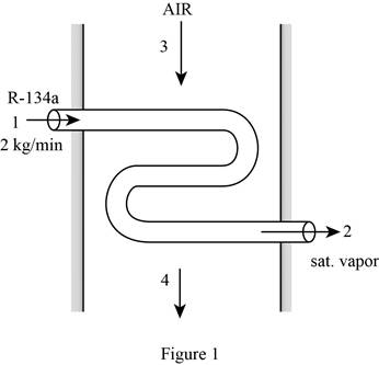
Draw the schematic diagram of the flow of refrigerant-134a through evaporator section as shown in Figure (1).
Write the expression for the mass balances equation for the heat exchanger.
Here, mass flow rate of refrigerant at inlet is
Since net mass flow rate of refrigerant-134a and air through system is 0.
From Figure (1), the mass flow rate of refrigerant-134a at
Here, initial and final mass flow rate of refrigerant at
From Figure (1), the mass flow rate of air at
Here, mass flow rate of air at
Write the expression for the enthalpy at state 1
Write the expression for the entropy at state 1
Write the expression for the mass flow rate of air
Here, gas constant of air is
Write the expression for energy balance for the heat exchanger
Here, rate of net energy transfer in to the control volume is
Substitute 0 for
Here, mass flow rate at
Write the expression for the entropy balance for the steady flow system as;
Here, rate of entropy generation is
At steady state, rate of change in entropy of the system is zero.
Substitute 0 for
Here, entropy at
Write the expression for the change between state 4 entropy
Here, temperature at state
Write the expression for the exergy destroyed rate during the process
Here, dead state temperature is
Conclusion:
Refer to Table A-12, “Saturated refrigerant-134a-Pressure table”, obtain the following properties at the pressure
Here, enthalpy of saturated liquid is
Substitute
Substitute
Refer to Table A-12, “Saturated refrigerant-134a-Pressure table”, obtain the following properties at the pressure
Here, enthalpy at state 2 is
From the Table A-2, “Ideal-gas specific heats of various common gases table”, select the gas constant of air gas
Substitute
At steady state, rate of change in internal energy of the system is zero.
From the Table A-2, “Ideal-gas specific heats of various common gases table”, select the constant pressure specific heat
Substitute
Thus, the exit temperature
Substitute
Substitute
Substitute
Thus, the rate of exergy destroyed during the process is
b)
The exit temperature of the air and the rate of exergy destroyed during the process without insulation.
b)
Answer to Problem 64P
The exit temperature of the air without insulation is
The rate of exergy destroyed during the process without insulation is
Explanation of Solution
Write the expression for the state 4 temperature
Here, heat gain is from the surrounding
Write the expression for the entropy balance For an extended system as;
Conclusion:
Substitute
Thus, the exit temperature of the air is
substitute
Substitute
Substitute
Thus, the rate of exergy destroyed during the process is
Want to see more full solutions like this?
Chapter 8 Solutions
THERMODYNAMICS CONNECT ACCESS CARD


- Hot combustion gases enter the nozzle of a turbojet engine at 230 kPa, 627°C, and 60 m/s and exit at 70 kPa and 450°C. Assuming the nozzle to be adiabatic and the surroundings to be at 20°C, determine the decrease in the exergy of the gases. Take k = 1.3 and cp = 1.15 kJ/kg·°C for the combustion gases.arrow_forwardDevices can be combined to perform a variety of tasks. An adiabatic compressor, with air as the working fluid, is to be powered by an adiabatic steam turbine, which is also driving a generator. Steam enters the turbine at 12.5 MPa and 500 ∘C at a steady rate of 27.30 kg/s and exits at 10 kPa and a quality of 0.8710. Air enters the compressor at 98 kPa and 295.0 K K at a steady rate of 12.600 kg/s and exits at 1 MPa and 635.0 K. For air, MW=29.0 g/mol, Cp=3.5R. Note: The IUPAC sign convention for work is used. Work into the system has a positive value. What is the magnitude of the power delivered to the generator by the turbine? The answer needs to be in MW.arrow_forwardRefrigerant-134a is to be compressed from 0.14 MPa and 10°C to 0.8 MPa and 50°C steadily by a compressor. Taking the environment conditions to be 20°C and 95kPa. Determine the EXERGY change of the refrigerant during this process and the minimum work input that needs to be supplied to the compressor per unit mass of the refrigerant. P.S please help me with this question, And please also show me your solution clearly. Thank you very much. Godblessarrow_forward
- Steam at 7 MPa and 400°C enters a two-stage adiabatic turbine at a rate of 15 kg/s. Ten percent of the steam is extracted at the end of the first stage at a pressure of 1.8 MPa for other use. The remainder of the steam is further expanded in the second stage and leaves the turbine at 10 kPa. If the turbine has an isentropic efficiency of 88 percent, determine the wasted power potential during this process as a result of irreversibilities. Assume the surroundings to be at 25°C.arrow_forwardRefrigerant-134a is condensed in a refrigeration system by rejecting heat to ambient air at 25°C. R-134a enters the condenser at 700 kPa and 50°C at a rate of 0.05 kg/s and leaves at the same pressure as a saturated liquid. Determine the rate of exergy destruction in the condenser.arrow_forwardConsider a thermal energy reservoir at 1500 K that can supply heat at a rate of 150,000 kJ/h. Determine the exergy of this supplied energy, assuming an environment temperature of 25°C.arrow_forward
- Refrigerant-134a at 140 kPa and 210C is compressed by an adiabatic 1.3-kW compressor to an exit state of 700 kPa and 60C. Neglecting the changes in kinetic and potential energies, determine (a) the isentropic efficiency of the compressor, (b) the volume flow rate of the refrigerant at the compressor inlet, in L/min, and (c) the maximum volume flow rate at the inlet conditions that this adiabatic 1.3-kW compressor can handle without violating the second law.arrow_forwardConsider two geothermal wells whose energy contents are estimated to be the same. Will the exergies of these wells necessarily be the same? Explain.arrow_forward14 - The volumetric flow rate of the refrigerant R-134a entering a compressor at 140 kPa pressure and – 10ºC temperature is 1.23 m³/min. What is the mass flow rate of R-134a? a) 0.7376 kg/h B) 0.1229 kg/h NS) 0.6804 kg/h D) 0.1404 kg/h TO) 0.1134 kg/harrow_forward
- Air is to be compressed steadily and isentropically from 1 atm to 16 atm by a two-stage compressor. To minimize the total compression work, the intermediate pressure between the two stages must be (a) 3 atm (b) 4 atm (c) 8.5 atm (d) 9 atm (e) 12 atmarrow_forwardDevices can be combined to perform a variety of tasks. An adiabatic compressor, with air as the working fluid, is to be powered by an adiabatic steam turbine, which is also driving a generator. Steam enters the turbine at 12.5 MPa and 500 ∘C500 ∘C at a steady rate of 27.30 kg/s27.30 kg/s and exits at 10 kPa and a quality of 0.8710.0.8710. Air enters the compressor at 98 kPa and 295.0 K295.0 K at a steady rate of 12.600 kg/s12.600 kg/s and exits at 1 MPa and 635.0 K.635.0 K. For air, MW=29.0 g/mol,MW=29.0 g/mol, ??=3.5R.Cp=3.5R. Note: The IUPAC sign convention for work is used. Work into the system has a positive value. What is the magnitude of the power delivered to the generator by the turbine?arrow_forwardRefrigerant-134a is to be cooled by water in a condenser. The refrigerant enters the condenser with a mass flow rate of 6 kg/min at 1 MPa and 70ºC and leaves at 35°C. The cooling water enters at 300 kPa and 15°C and leaves at 25ºC. Neglecting any pressure drops, determine (a) the mass flow rate of the cooling water required and (b) the heat transfer rate from the refrigerant to waterarrow_forward
 Elements Of ElectromagneticsMechanical EngineeringISBN:9780190698614Author:Sadiku, Matthew N. O.Publisher:Oxford University Press
 Mechanics of Materials (10th Edition)Mechanical EngineeringISBN:9780134319650Author:Russell C. HibbelerPublisher:PEARSON
 Thermodynamics: An Engineering ApproachMechanical EngineeringISBN:9781259822674Author:Yunus A. Cengel Dr., Michael A. BolesPublisher:McGraw-Hill Education
 Control Systems EngineeringMechanical EngineeringISBN:9781118170519Author:Norman S. NisePublisher:WILEY
 Mechanics of Materials (MindTap Course List)Mechanical EngineeringISBN:9781337093347Author:Barry J. Goodno, James M. GerePublisher:Cengage Learning
 Engineering Mechanics: StaticsMechanical EngineeringISBN:9781118807330Author:James L. Meriam, L. G. Kraige, J. N. BoltonPublisher:WILEY