
Introductory Circuit Analysis (13th Edition)
13th Edition
ISBN: 9780133923605
Author: Robert L. Boylestad
Publisher: PEARSON
expand_more
expand_more
format_list_bulleted
Videos
Textbook Question
Chapter 9, Problem 10P
a. Find the Thévenin equivalent circuit for the network external to the resistor R for the network in Fig.9.134.
b. Find the power delivered to R when R is 2k
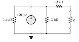
Fig.9.134
Expert Solution & Answer
Want to see the full answer?
Check out a sample textbook solution
Students have asked these similar questions
Find this results using Multisim/Pspice Software,
PLEASE HELP ASAP
given circuit, Vk = 12 V, R = 240 Ω, C = 1 μF, L = 40 mH. Theswitch, is closed for a long time for t < 0– . Determine vL(t) for t > 0.
Calculate Vo(t) in the circuit of Fig. 9.49.
Chapter 9 Solutions
Introductory Circuit Analysis (13th Edition)
Ch. 9 - (a) Using the superposition theorem, determine the...Ch. 9 - a. Using the superposition theorem, determine the...Ch. 9 - Using the superposition theorem, determine the...Ch. 9 - Using superposition, find the current l through...Ch. 9 - Using superposition, find the voltage VR3 for the...Ch. 9 - Using superposition, find the voltage V2 for the...Ch. 9 - Using superposition, find the current through R1...Ch. 9 - Using superposition, find the voltage across the...Ch. 9 - a. Find the Thévenin equivalent circuit for the...Ch. 9 - a. Find the Thévenin equivalent circuit for the...
Ch. 9 - a. Find the Thévenin equivalent circuit for the...Ch. 9 - Find the Thévenin equivalent circuit for the...Ch. 9 - Find the Thévenin equivalent circuit for the...Ch. 9 - Find the Thévenin equivalent circuit for the...Ch. 9 - a. Find the Thévenin equivalent circuit for the...Ch. 9 - Determine the Thevénin equivalent circuit for the...Ch. 9 - a. Determine the Thévenin equivalent circuit for...Ch. 9 - For the network in Fig. 9.142, find the Thévenin...Ch. 9 - For the transistor network in Fig. 9.143. a. Find...Ch. 9 - For each vertical set of measurements appearing in...Ch. 9 - For the network of Fig.9.145, find the Thévenin...Ch. 9 - a. Find the Norton equivalent circuit for the...Ch. 9 - a. Find the Norton equivalent circuit for the...Ch. 9 - Find the Norton equivalent circuit for the network...Ch. 9 - Find the Norton equivalent circuit for the network...Ch. 9 - Find the Norton equivalent circuit for the network...Ch. 9 - Find the Norton equivalent circuit for the network...Ch. 9 - Find the Norton equivalent circuit for the network...Ch. 9 - Find the Norton equivalent circuit for the network...Ch. 9 - a. Find the Norton equivalent circuit external to...Ch. 9 - a. Find the value of R for maximum power transfer...Ch. 9 - a. Find the value of R for maximum power transfer...Ch. 9 - a. Find the value of R for maximum power transfer...Ch. 9 - a. Find the value of RL in Fig.9.142 for maximum...Ch. 9 - a. For the network of Fig. 9.147, determine the...Ch. 9 - Find the resistance R1 in Fig.9.148 such that the...Ch. 9 - a. For the network in Fig.9.149, determine the...Ch. 9 - For the network in Fig. 9.150, determine the level...Ch. 9 - Using Millmans theorem, find the current through...Ch. 9 - Repeat Problem 38 for the network in Fig.9.152....Ch. 9 - Using Millmans theorem, find the current through...Ch. 9 - Using the dual of Millmans theorem, find the...Ch. 9 - Using the dual of Millmans theorem, find the...Ch. 9 - Using the substitution theorem, draw three...Ch. 9 - Using the substituion theorem, draw three...Ch. 9 - Using the substitution theorem, draw three...Ch. 9 - a. For the network in Fig. 9.159(a), determine the...Ch. 9 - a. For the network of Fig.9.16(a), determine the...Ch. 9 - a. Determine the voltageV for the network in...Ch. 9 - Using PSpice or Multisim and the superposition...Ch. 9 - Using PSpice or Multisim, determine the Thévenin...Ch. 9 - a. Using PSpice, plot the power delivered to the...Ch. 9 - Change the 300 resistor in Fig. 9.145 to a...
Additional Engineering Textbook Solutions
Find more solutions based on key concepts
When travelers from the USA and Canada visit Europe, they encounter a different power distribution system. Wall...
Electric machinery fundamentals
How many coulombs do 93.8 1016 electrons represent?
Principles Of Electric Circuits
Electric power systems provide energy in a variety of commercial and industrial settings. Make a list of system...
Principles and Applications of Electrical Engineering
Identify the type of input and output configuration for each diff-amp in Figure 18-35.
Electronics Fundamentals: Circuits, Devices & Applications
Does the severity of an electric shock increase ordecrease with eh of the following changes? a. A decrease in t...
Electric Motors and Control Systems
Design an ideal inverting op-amp circuit such that the voltage gain is Av=25 . The maximum current in any resis...
Microelectronics: Circuit Analysis and Design
Knowledge Booster


Learn more about
Need a deep-dive on the concept behind this application? Look no further. Learn more about this topic, electrical-engineering and related others by exploring similar questions and additional content below.Similar questions
- RLC LTI Systems with DC Source Let: R = 10 Ohms C = 10-2 Farads L = 0.5 Henry E = 12 V Assuming q(0) = 0 and i(0) = 0, find the current in the system.arrow_forwardA circuit is given below. Compute for the algebraic sum of potential difference for the following electrical loops using KVL: abca abdca acda abcda acbda Show your systematic solutions.arrow_forwardThe sinusoidal voltage source in the circuit isdeveloping a voltage equal to 50 sin 400t V.1. Find the Thévenin voltage with respect to the terminals a,b.2. Find the Thévenin impedance with respect to the terminals a,b.3. Draw the Thévenin equivalentarrow_forward
- Calculate in the circuit of Fig. 9.51.arrow_forwardTwo voltages can be represented by the following phasors: V1=(12+6j) V2=(4+5j) Work out the resultant phasors of the two voltage supply combined, i.e. VR=V1+V2 Convert the V1 and V2 phasors to polar forms, together with V1+V2. Using the phasors diagram, Determine the resultant VR graphicallyarrow_forwardCircuits Determine Vx using Nodal Analysis. Give the step-by-step solution.arrow_forward
- Write an expression for the output voltage vo(t) ofthe circuit shown if R1 = 1 k , R2 =2 k , R3 =47 k , v2(t)=(0.01 sin 3770t) V, andv1(t)=(0.04 sin 10000t)V. Write an expression forthe voltage appearing at the summing junction (v−).arrow_forwardPlease answer quickly "In ac circuits, Kirchhoff s Voltage Law (KVL) states that in any given electric network, the phasor sum of the voltage rises and voltage drops within a node is always equal to zero." True False In ac circuit solution using KCL, the maximum number of independent equation/s can be used is equal to the number of major nodes." True False Norton's theorem is a network analysis method that allows a portion of a circuit to be isolated while the remianing portion of the network is replaced with an equivalent network (a parallel voltage source to an equivalent impedance). True Falsearrow_forwardThe admittance for a circuit, G + jB, is 0.02 + j0.20. What is the impedance, R + jX? Provide illustration of the circuit.arrow_forward
arrow_back_ios
arrow_forward_ios
Recommended textbooks for you
 Introductory Circuit Analysis (13th Edition)Electrical EngineeringISBN:9780133923605Author:Robert L. BoylestadPublisher:PEARSON
 Delmar's Standard Textbook Of ElectricityElectrical EngineeringISBN:9781337900348Author:Stephen L. HermanPublisher:Cengage Learning
 Programmable Logic ControllersElectrical EngineeringISBN:9780073373843Author:Frank D. PetruzellaPublisher:McGraw-Hill Education
 Fundamentals of Electric CircuitsElectrical EngineeringISBN:9780078028229Author:Charles K Alexander, Matthew SadikuPublisher:McGraw-Hill Education
 Electric Circuits. (11th Edition)Electrical EngineeringISBN:9780134746968Author:James W. Nilsson, Susan RiedelPublisher:PEARSON
 Engineering ElectromagneticsElectrical EngineeringISBN:9780078028151Author:Hayt, William H. (william Hart), Jr, BUCK, John A.Publisher:Mcgraw-hill Education,
Introductory Circuit Analysis (13th Edition)
Electrical Engineering
ISBN:9780133923605
Author:Robert L. Boylestad
Publisher:PEARSON
Delmar's Standard Textbook Of Electricity
Electrical Engineering
ISBN:9781337900348
Author:Stephen L. Herman
Publisher:Cengage Learning
Programmable Logic Controllers
Electrical Engineering
ISBN:9780073373843
Author:Frank D. Petruzella
Publisher:McGraw-Hill Education
Fundamentals of Electric Circuits
Electrical Engineering
ISBN:9780078028229
Author:Charles K Alexander, Matthew Sadiku
Publisher:McGraw-Hill Education
Electric Circuits. (11th Edition)
Electrical Engineering
ISBN:9780134746968
Author:James W. Nilsson, Susan Riedel
Publisher:PEARSON
Engineering Electromagnetics
Electrical Engineering
ISBN:9780078028151
Author:Hayt, William H. (william Hart), Jr, BUCK, John A.
Publisher:Mcgraw-hill Education,
Lesson 2 - Source Transformations, Part 2 (Engineering Circuits); Author: Math and Science;https://www.youtube.com/watch?v=7gno74RhVGQ;License: Standard Youtube License