
Introductory Circuit Analysis (13th Edition)
13th Edition
ISBN: 9780133923605
Author: Robert L. Boylestad
Publisher: PEARSON
expand_more
expand_more
format_list_bulleted
Concept explainers
Videos
Textbook Question
Chapter 9, Problem 20P
For each vertical set of measurements appearing in Fig.9.144, determine the Thevenin equivalent circuit.
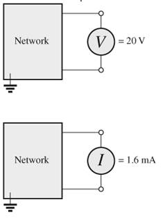
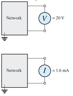
Fig.9.144
Expert Solution & Answer
Want to see the full answer?
Check out a sample textbook solution
Students have asked these similar questions
Use source transformation to calculate the voltage Vo, if Is = 9, R = 9 and Vs = 1.
Calculate i(t) in the circuit of Fig. 9.51.
The sinusoidal voltage source in the circuit isdeveloping a voltage equal to 50 sin 400t V.1. Find the Thévenin voltage with respect to the terminals a,b.2. Find the Thévenin impedance with respect to the terminals a,b.3. Draw the Thévenin equivalent
Chapter 9 Solutions
Introductory Circuit Analysis (13th Edition)
Ch. 9 - (a) Using the superposition theorem, determine the...Ch. 9 - a. Using the superposition theorem, determine the...Ch. 9 - Using the superposition theorem, determine the...Ch. 9 - Using superposition, find the current l through...Ch. 9 - Using superposition, find the voltage VR3 for the...Ch. 9 - Using superposition, find the voltage V2 for the...Ch. 9 - Using superposition, find the current through R1...Ch. 9 - Using superposition, find the voltage across the...Ch. 9 - a. Find the Thévenin equivalent circuit for the...Ch. 9 - a. Find the Thévenin equivalent circuit for the...
Ch. 9 - a. Find the Thévenin equivalent circuit for the...Ch. 9 - Find the Thévenin equivalent circuit for the...Ch. 9 - Find the Thévenin equivalent circuit for the...Ch. 9 - Find the Thévenin equivalent circuit for the...Ch. 9 - a. Find the Thévenin equivalent circuit for the...Ch. 9 - Determine the Thevénin equivalent circuit for the...Ch. 9 - a. Determine the Thévenin equivalent circuit for...Ch. 9 - For the network in Fig. 9.142, find the Thévenin...Ch. 9 - For the transistor network in Fig. 9.143. a. Find...Ch. 9 - For each vertical set of measurements appearing in...Ch. 9 - For the network of Fig.9.145, find the Thévenin...Ch. 9 - a. Find the Norton equivalent circuit for the...Ch. 9 - a. Find the Norton equivalent circuit for the...Ch. 9 - Find the Norton equivalent circuit for the network...Ch. 9 - Find the Norton equivalent circuit for the network...Ch. 9 - Find the Norton equivalent circuit for the network...Ch. 9 - Find the Norton equivalent circuit for the network...Ch. 9 - Find the Norton equivalent circuit for the network...Ch. 9 - Find the Norton equivalent circuit for the network...Ch. 9 - a. Find the Norton equivalent circuit external to...Ch. 9 - a. Find the value of R for maximum power transfer...Ch. 9 - a. Find the value of R for maximum power transfer...Ch. 9 - a. Find the value of R for maximum power transfer...Ch. 9 - a. Find the value of RL in Fig.9.142 for maximum...Ch. 9 - a. For the network of Fig. 9.147, determine the...Ch. 9 - Find the resistance R1 in Fig.9.148 such that the...Ch. 9 - a. For the network in Fig.9.149, determine the...Ch. 9 - For the network in Fig. 9.150, determine the level...Ch. 9 - Using Millmans theorem, find the current through...Ch. 9 - Repeat Problem 38 for the network in Fig.9.152....Ch. 9 - Using Millmans theorem, find the current through...Ch. 9 - Using the dual of Millmans theorem, find the...Ch. 9 - Using the dual of Millmans theorem, find the...Ch. 9 - Using the substitution theorem, draw three...Ch. 9 - Using the substituion theorem, draw three...Ch. 9 - Using the substitution theorem, draw three...Ch. 9 - a. For the network in Fig. 9.159(a), determine the...Ch. 9 - a. For the network of Fig.9.16(a), determine the...Ch. 9 - a. Determine the voltageV for the network in...Ch. 9 - Using PSpice or Multisim and the superposition...Ch. 9 - Using PSpice or Multisim, determine the Thévenin...Ch. 9 - a. Using PSpice, plot the power delivered to the...Ch. 9 - Change the 300 resistor in Fig. 9.145 to a...
Additional Engineering Textbook Solutions
Find more solutions based on key concepts
With respect to the circuit in Fig. 5.90, (a) employ Thévenin’s theorem to determine the equivalent network see...
Loose Leaf for Engineering Circuit Analysis Format: Loose-leaf
How many coulombs do 93.8 1016 electrons represent?
Principles Of Electric Circuits
Three point charges of equal magnitude q, that will yield a zero net electric field at the origin.
Engineering Electromagnetics
Electric power systems provide energy in a variety of commercial and industrial settings. Make a list of system...
Principles and Applications of Electrical Engineering
Does the severity of an electric shock increase ordecrease with eh of the following changes? a. A decrease in t...
Electric Motors and Control Systems
Find I0 and I1 in the circuit in Fig.P2.12.
Basic Engineering Circuit Analysis
Knowledge Booster


Learn more about
Need a deep-dive on the concept behind this application? Look no further. Learn more about this topic, electrical-engineering and related others by exploring similar questions and additional content below.Similar questions
- The voltage v = 294 sin(100t-35°) V is connected acroos a 1-µF capacitor. Determine the current in polar form. Write the angle in degrees only in four decimal places.arrow_forwardA microstrip transmission line is to be used as a capacitor of 4pf at 800MHZ. The PCB dielectric is 3.6. The microstrip dimensions are h= 0.0625in, w= 0.13in, and l=0.002in.What are (a) the characteristic impedance of the line and (b) the reactance of the capacitor.arrow_forwardQuestion 9.15 (a) For the network of Fig. 9.75:a. Determine reB. Locate Avmedia=VO/VsC. Calculate Ziarrow_forward
- A 3-phase, 50 Hz, 400 V motor input power is 84000W the power factor being 0.72 lagging. A bank of capacitors is connected in delta across the supply terminals and the power factor raised to 0.89 lagging. Each of the capacitance units is built of 4 similar 100 V capacitors. Determine the capacitance of each capacitor. Capacitance = _________________ Faradarrow_forwardThe admittance for a circuit, G + jB, is 0.02 + j0.20. What is the impedance, R + jX? Provide illustration of the circuit.arrow_forwardA 480-V rms, 60 Hz source supplies a load having a total impedance of 50 angle 60° ohms. Find the capacitance of a parallel capacitor that will correct the overall power factor to 0.9 lagging.arrow_forward
- A capacitor of 3.18 microfarads is connected in parallel with a resistance of 2000 ohms. The combination is further connected in series with an inductance of 795 mH and resistance of 100 ohms across a supply given by e=400 sinwt + 80 sin( 3w+60). Asusme w=314 radians per sec. Determine the circuit power factor.arrow_forwardGiven the following pairs of voltages and currents, indicate whether the element involved is a capacitor, an inductor, or a resistor, and determine the values of C, L or R. (if sufficient data are given) a.) v = 550 sin(377t + 50°); i = 11 sin(377t − 40°) b.) v = 36 sin(754t − 80°); i = 4 sin(754t − 170°) c.) v = 10.5 sin(ωt − 13°); i = 1.5 sin(ωt − 13°)arrow_forwardQ20/ choose the correct answer R-2R ladder network DAC operates at high speed. Select one: True Falsearrow_forward
- A circuit is given below. Compute for the algebraic sum of potential difference for the following electrical loops using KVL: abca abdca acda abcda acbda Show your systematic solutions.arrow_forwardIf a phasor representation of a current is given by I = 70.7 ∠45° A, it is equivalent toarrow_forward4. Voltage flows through an electric circuit like water flows through a pipe. Select one: TRUE FALSEarrow_forward
arrow_back_ios
SEE MORE QUESTIONS
arrow_forward_ios
Recommended textbooks for you
 Introductory Circuit Analysis (13th Edition)Electrical EngineeringISBN:9780133923605Author:Robert L. BoylestadPublisher:PEARSON
 Delmar's Standard Textbook Of ElectricityElectrical EngineeringISBN:9781337900348Author:Stephen L. HermanPublisher:Cengage Learning
 Programmable Logic ControllersElectrical EngineeringISBN:9780073373843Author:Frank D. PetruzellaPublisher:McGraw-Hill Education
 Fundamentals of Electric CircuitsElectrical EngineeringISBN:9780078028229Author:Charles K Alexander, Matthew SadikuPublisher:McGraw-Hill Education
 Electric Circuits. (11th Edition)Electrical EngineeringISBN:9780134746968Author:James W. Nilsson, Susan RiedelPublisher:PEARSON
 Engineering ElectromagneticsElectrical EngineeringISBN:9780078028151Author:Hayt, William H. (william Hart), Jr, BUCK, John A.Publisher:Mcgraw-hill Education,
Introductory Circuit Analysis (13th Edition)
Electrical Engineering
ISBN:9780133923605
Author:Robert L. Boylestad
Publisher:PEARSON
Delmar's Standard Textbook Of Electricity
Electrical Engineering
ISBN:9781337900348
Author:Stephen L. Herman
Publisher:Cengage Learning
Programmable Logic Controllers
Electrical Engineering
ISBN:9780073373843
Author:Frank D. Petruzella
Publisher:McGraw-Hill Education
Fundamentals of Electric Circuits
Electrical Engineering
ISBN:9780078028229
Author:Charles K Alexander, Matthew Sadiku
Publisher:McGraw-Hill Education
Electric Circuits. (11th Edition)
Electrical Engineering
ISBN:9780134746968
Author:James W. Nilsson, Susan Riedel
Publisher:PEARSON
Engineering Electromagnetics
Electrical Engineering
ISBN:9780078028151
Author:Hayt, William H. (william Hart), Jr, BUCK, John A.
Publisher:Mcgraw-hill Education,
Current Divider Rule; Author: Neso Academy;https://www.youtube.com/watch?v=hRU1mKWUehY;License: Standard YouTube License, CC-BY