
MECH ENGINEERING DESIGN(LL)+ACCESS
10th Edition
ISBN: 9781260113952
Author: BUDYNAS
Publisher: MCG
expand_more
expand_more
format_list_bulleted
Videos
Textbook Question
Chapter 9, Problem 35P
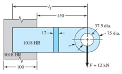
The attachment shown carries a static bending load of 12 kN. The attachment length, l1, is 225 mm. Specify the weldment (give the pattern, electrode number, type of weld, length of weld, and leg size).
Problem 9–35
Dimensions in millimeters.
Expert Solution & Answer
Want to see the full answer?
Check out a sample textbook solution
Students have asked these similar questions
Question No. 11: (a) Illustrate flatness, straightness and circularity with symbol.
(b) A circular shaft, 80 mm in diameter is welded to support by means of a circumferential fillet weld. It is
subjected to a torsion moment of 3000 N-m. Determine the size of weld, if the maximum shear stress in the weld
is not to exceed 70 N/mm2
.
(c) Analyze different stresses during design of screw and nut
The figure shows a solid 2-inch diameter roller that is attached to the wall by means of a permanent clamping. Specify the weld size for the case where the maximum allowable shear stress is 18 kpsi.
Help me to find the Smallest allowable cross section area of member BD, DE and CE Thankss
Chapter 9 Solutions
MECH ENGINEERING DESIGN(LL)+ACCESS
Ch. 9 - 91 to 94 The figure shows a horizontal steel bar...Ch. 9 - 91 to 94 The figure shows a horizontal steel bar...Ch. 9 - 91 to 94 The figure shows a horizontal steel bar...Ch. 9 - 91 to 94 The figure shows a horizontal steel bar...Ch. 9 - 95 to 98 For the weldments of Probs. 91 to 94, the...Ch. 9 - 95 to 98 For the weldments of Probs. 91 to 94, the...Ch. 9 - 95 to 98 For the weldments of Probs. 91 to 94, the...Ch. 9 - 95 to 98 For the weldments of Probs. 91 to 94, the...Ch. 9 - 99 to 912 The materials for the members being...Ch. 9 - Prob. 10P
Ch. 9 - Prob. 11PCh. 9 - 99 to 912 The materials for the members being...Ch. 9 - 913 to 916 A steel bar of thickness h is welded to...Ch. 9 - 913 to 916 A steel bar of thickness h is welded to...Ch. 9 - 913 to 916 A steel bar of thickness h is welded to...Ch. 9 - Prob. 16PCh. 9 - Prob. 17PCh. 9 - 917 to 920 A steel bar of thickness h, to be used...Ch. 9 - 917 to 920 A steel bar of thickness h, to be used...Ch. 9 - 917 to 920 A steel bar of thickness h, to be used...Ch. 9 - Prob. 21PCh. 9 - 921 to 924 The figure shows a weldment just like...Ch. 9 - Prob. 23PCh. 9 - Prob. 24PCh. 9 - 9-25 to 9-28 The weldment shown in the figure is...Ch. 9 - 9-25 to 9-28 The weldment shown in the figure is...Ch. 9 - Prob. 27PCh. 9 - 925 to 928 The weldment shown in the figure is...Ch. 9 - The permissible shear stress for the weldment...Ch. 9 - Prob. 30PCh. 9 - 9-30 to 9-31 A steel bar of thickness h is...Ch. 9 - In the design of weldments in torsion it is...Ch. 9 - Prob. 33PCh. 9 - Prob. 34PCh. 9 - The attachment shown carries a static bending load...Ch. 9 - The attachment in Prob. 935 has not had its length...Ch. 9 - Prob. 37PCh. 9 - Prob. 39PCh. 9 - Prob. 40PCh. 9 - Prob. 42PCh. 9 - 9-43 to 9-45 A 2-in dia. steel bar is subjected to...Ch. 9 - 9-43 to 9-45 A 2-in dia. steel bar is subjected to...Ch. 9 - Prob. 45PCh. 9 - Prob. 46PCh. 9 - Find the maximum shear stress in the throat of the...Ch. 9 - The figure shows a welded steel bracket loaded by...Ch. 9 - Prob. 49PCh. 9 - Prob. 50PCh. 9 - Prob. 51PCh. 9 - Brackets, such as the one shown, are used in...Ch. 9 - For the sake of perspective it is always useful to...Ch. 9 - Hardware stores often sell plastic hooks that can...Ch. 9 - For a balanced double-lap joint cured at room...
Knowledge Booster


Learn more about
Need a deep-dive on the concept behind this application? Look no further. Learn more about this topic, mechanical-engineering and related others by exploring similar questions and additional content below.Similar questions
- The double-offset joint is typically used in applica tions that require______. a. higher operating angles and greater plunge depth b. lower operating angles and lower plunge depth c. higher operating angles and lower plunge depth d. lower operating angles and greater plunge deptharrow_forwardThe arm in the figure is combined with a rod with a diameter of d=30 mm and a neck (corner) weld of a=5 mm thickness to the rod wall sourced with. The force acting on the arm is F=2 kN. The lengths are L1=L2=100 mm. Joined parts St37-2 (ak=235 N/mm2 ) made of material. Welding is I. Quality and has no impact effect. Check if the source in zone A is safe. Please pay. (S=1.5 V1=0.8)arrow_forwardThe arm in the figure is combined with a rod with a diameter of d=30 mm and a neck (corner) weld with a thickness of a= 5mm to the rod wall.sourced with. The force acting on the arm is F=2 kN. The lengths are L1=L2=100 mm. Joined parts are made of St37-2 (ak=235 N/mm2) material. Welding is I. Quality and has no impact effect. Check if the source in zone A is safe. (S=1.5 V1=0.8)arrow_forward
- Calculate the internal force (positive if tensile, negative if compressive) in rod (3). Use a FBD cutting through the rod in the section that includes the free end A.Answer: F3 = Enter your answer in accordance to the question statement kips.arrow_forwardRepeat question but with the load at joint 1 acting horizontally?arrow_forwardSolve the following using Truss Analysis: 2. Method of section (choose any section cut)arrow_forward
- The flange coupling for two shafts made of plain carbon steel to be connected. The shafts transmitting a toque of 600 N-m. Assume the following permissible stresses for the coupling components: Shaft — Permissible shear stress = 35 MPa Keys — Rectangular formed end sunk key having permissible compressive strength = 60 MPa Bolts — Six numbers made of steel having permissible shear stress = 28 MPa Pitch circle diameter of bolts = 1.6 × Diameter of shaft Calculate: 1. diameter of shaft; 2. Hub length 3. Hub diameter 2. thickness of flange; 3. Diameter of flange 4. Width of key 5. Thickness of key 5. Diameter of bolt; 6. Crashing stress in boltarrow_forwardA horizontal plate using four rivets arranged as shown in figure. Determine the magnitude of the load?arrow_forwardThe carrier plate material St52 (S355) given in the figure below is welded to the body. combined. F1 = 4 kN and F2 = 40 kN static forces act on the plate. Source I. Quality (v2 = 1), no impact (v3 = 1), weld thickness a = 5 mm, safety coefficient s = 2 and weld seam coefficient v1 = 0.8 will be taken. Find out whether a = 5 mm weld seam thickness is sufficient or not, according to the data in the figure and above.arrow_forward
- What is the factor of safety when a 0.50-in, 6 x 19 medium plow steel wire rope carrying an 8800 lb load is bent around a 25-in sheave if the breaking strength of the rope is 8.5 tons?arrow_forwardTwo 1/4 in × 8 in A36 steel plates are joined with a lap joint using 3/4 in A325-N bolts. If a concentric unfactored live load of 50 kips (dead load = 0) is required to be resisted by the connection and the bolt shear strength controls the design, the minimum required number of bolts is?arrow_forward7(b) For the following joint as shown in Figure 6, write the number of prismatic joints and revolute joints. What is the name of the combined system?arrow_forward
arrow_back_ios
SEE MORE QUESTIONS
arrow_forward_ios
Recommended textbooks for you
 Automotive Technology: A Systems Approach (MindTa...Mechanical EngineeringISBN:9781133612315Author:Jack Erjavec, Rob ThompsonPublisher:Cengage Learning
 Welding: Principles and Applications (MindTap Cou...Mechanical EngineeringISBN:9781305494695Author:Larry JeffusPublisher:Cengage Learning
Automotive Technology: A Systems Approach (MindTa...
Mechanical Engineering
ISBN:9781133612315
Author:Jack Erjavec, Rob Thompson
Publisher:Cengage Learning
Welding: Principles and Applications (MindTap Cou...
Mechanical Engineering
ISBN:9781305494695
Author:Larry Jeffus
Publisher:Cengage Learning
Differences between Temporary Joining and Permanent Joining.; Author: Academic Gain Tutorials;https://www.youtube.com/watch?v=PTr8QZhgXyg;License: Standard Youtube License