
Videos
Using Fig. 9.45, design a problem to help other students better understand admittance.
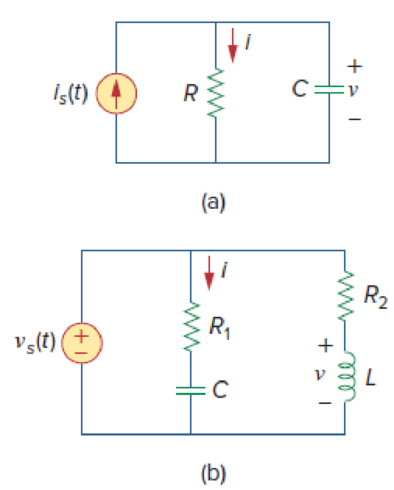
Figure 9.45
Design a problem to make better understand about the admittance using Figure 9.45.
Explanation of Solution
Problem design:
Determine the value of current
Formula used:
Write the expression to convert the time domain expression into phasor domain.
Here,
A is the magnitude,
t is the time, and
Write the expression to calculate the impedance of the passive elements resistor, inductor and capacitor.
Here,
Calculation:
(a)
The Figure 9.45(a) is redrawn as Figure 1 by assuming the values for the respective elements.
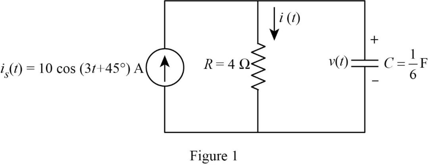
Refer to Figure 1, the current equation is,
Here, angular frequency
Use the equation (1) to express the above equation in phasor form.
Substitute
Substitute
The Figure 1 is redrawn as impedance circuit in the following Figure 2.
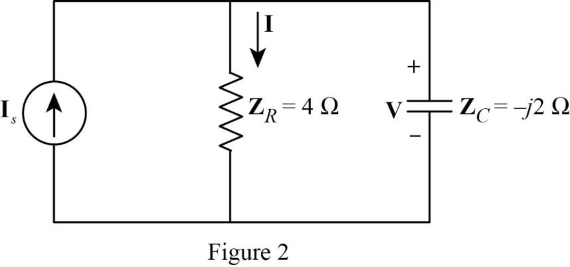
Apply current division rule on Figure 2 to find
Substitute
Use the equation (1) to express the above equation in time domain form.
Substitute
Refer to Figure 2, the voltage across the impedance
Substitute
Use the equation (1) to express the above equation in time domain form.
Substitute
Therefore, the value of current
(b)
The Figure 9.45(b) is redrawn as Figure 3 by assuming the values for the respective elements.
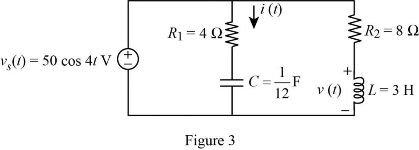
Refer to Figure 3, the voltage equation is,
Here, angular frequency
Use the equation (1) to express the above equation in phasor form.
Substitute
Substitute
Substitute
Substitute
The Figure 3 is redrawn as impedance circuit in the following Figure 4.
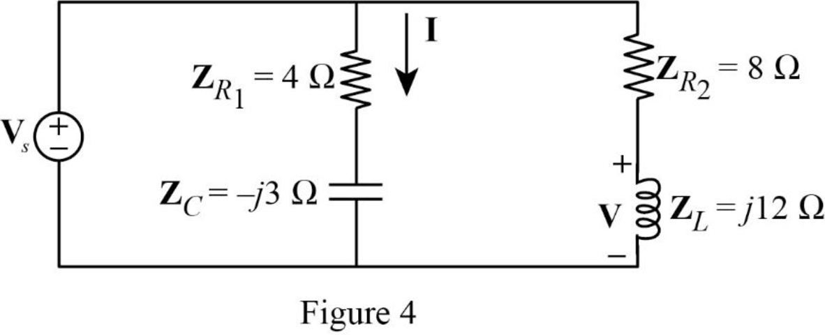
Refer to Figure 4, the impedances
Write the expression to calculate the equivalent impedance of the series connected impedances
Refer to Figure 4, the source voltage
Write the expression to calculate the current
Substitute
Substitute
Use the equation (1) to express the above equation in time domain form.
Substitute
Apply voltage division rule on Figure 4 to find
Substitute
Use the equation (1) to express the above equation in time domain form.
Substitute
Therefore, the value of current
Conclusion:
Thus, the problem to make better understand about the admittance using Figure 9.45 is designed.
Want to see more full solutions like this?
Chapter 9 Solutions
EBK FUNDAMENTALS OF ELECTRIC CIRCUITS


- The ac bridge circuit of Fig. 9.85 is called a Wien bridge. It is used for measuring the frequency of a source. Show that when the bridge is balanced, 1 f= 2π VR₂R₂C₂C₂ R₁ www C₂ AC meter ww R3 R₁ C4arrow_forwardFind current in the circuit shown in Fig. 9.50.arrow_forwardThe capacitive reactance is high when the capacitance and frequency of voltage source is high. Select one: True Falsearrow_forward
- Calculate the value of Zab in the network of Fig. 9.79. -19 2 a o j6 2 792 -192 20 2 20 2 102 bo elearrow_forward9.60 Obtain Zin for the circuit in Fig. 9.67. 50 Ω j30 Ω -j100 Ω — Lin 40 Ω Figure 9.67 For Prob. 9.60. www 60 Ω 120 Ωarrow_forward9. Recall that Kirchhoff's laws help to get the current in circuits. Consider the following circuit: L R I(t) C +q(t) -q(t) Ignore the alternating power for this problem. a) What is the voltage over the resistor if it has a resistance of R ohms and the current is I ampere? b) What is the voltage over the capacitor if the capacitance is C and the charge on the capacitor is q. c) What is the voltage over the inductor if it has an inductance of L Henry? The answer must be in a form of a differential equation.arrow_forward
- Consider the parallel and series combinations of the capacitors shown below. What is the equivalent capacitance between the terminals a and b. 6 F C₁ 6 F C1 3 F C2 82 + VC b I HE b 1₂ + VCI +1 VC2 3 F وتا Ceq 1. B Cea b b 16+ VC +arrow_forwardA series RC circuit consist of R = 2 mega-ohms and an uncharged capacitor C = 5 micro farad. The circuit is connected across a 100 V dc source at t = 0. Determine the voltage across the resistor 5 seconds later.arrow_forward9.44 Calculate i(t) in the circuit of Fig. 9.51. 5Ω 5 mF www 50 cos 200t V Figure 9.51 For prob. 9.44. 4 Ω ell 10 mH www 352arrow_forward
- Select all correct statement(s):1, The equivalent resistance for resistors in parallel is the harmonic mean of all resistors;2, The equivalent capacitance for capacitors in series is the sum of all capacitors;3, The equivalent inductance for inductors in series is the sum of all resistors.32None of them is correct1arrow_forwardAsiacell 9:11 O %01 令.l .ll Asiacell HOMEWORK An A.C. bridge has the following parameters Arm (AB): R1= 1KO, C1 = 1µF, Arm (AD): R2 = 3KO, L2 = 1mH, Arm (BC): R3= 2KO, Arm (DC) unknown cimpedance (Zx) The source is connected between (AC) the voltage is 10V with frequency is 1KHZ What would the resonant frequency of a Wien bridge circuit be if the resistors are 400 K2 and .capacitors are 0.4 µF An AC bridge is balanced at 2KHZ with the following components in each arm: Arm AB=10KO, Arm BC=100µF in series with 100KO, Arm AD=50KO Find the unknown impendence R+ X in the am DC, if the detector is between BD 10arrow_forwardd. 10dB A capacitor C = 50 µF is operating at 220 V at a frequency of 50HZ. The real power dissipated in this capacitor is Select one: O 100 W O Non of the Answers O200 W 150W O e 4) a ENG 12- TOSHIBAarrow_forward
 Introductory Circuit Analysis (13th Edition)Electrical EngineeringISBN:9780133923605Author:Robert L. BoylestadPublisher:PEARSON
 Delmar's Standard Textbook Of ElectricityElectrical EngineeringISBN:9781337900348Author:Stephen L. HermanPublisher:Cengage Learning
 Programmable Logic ControllersElectrical EngineeringISBN:9780073373843Author:Frank D. PetruzellaPublisher:McGraw-Hill Education
 Fundamentals of Electric CircuitsElectrical EngineeringISBN:9780078028229Author:Charles K Alexander, Matthew SadikuPublisher:McGraw-Hill Education
 Electric Circuits. (11th Edition)Electrical EngineeringISBN:9780134746968Author:James W. Nilsson, Susan RiedelPublisher:PEARSON
 Engineering ElectromagneticsElectrical EngineeringISBN:9780078028151Author:Hayt, William H. (william Hart), Jr, BUCK, John A.Publisher:Mcgraw-hill Education,