
EBK FUNDAMENTALS OF ELECTRIC CIRCUITS
6th Edition
ISBN: 8220102801448
Author: Alexander
Publisher: YUZU
expand_more
expand_more
format_list_bulleted
Concept explainers
Videos
Textbook Question
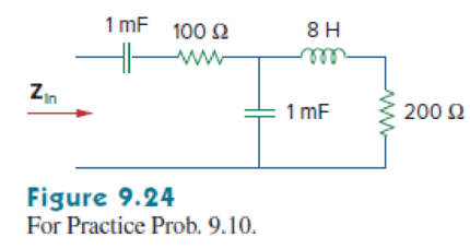
Chapter 9.7, Problem 10PP
Determine the input impedance of the circuit in Fig. 9.24 at
Expert Solution & Answer

Trending nowThis is a popular solution!

Students have asked these similar questions
An industrial coil is modeled as a series combination
...
of an inductance L and resistance R, as shown in
Fig. 9.90. Since an ac voltmeter measures only
the magnitude of a sinusoid, the following
measurements are taken at 60 Hz when the circuit
operates in the steady state:
80 Ω
Coil
ww
V
E
L
Decermine Rit.
E = 193 V
V1 = 67 V
Vo = 104 V
Round your answer to 4 decimal places.
all
Power in Extreme Frequency Limits. You and your team have been assigned to find a power supply for the circuit in the drawing.
which can be used to supply a dc voltage at 15.0 V, or a high frequency ac signal with a root-mean-square (rms) voltage of 15.0 V. The
components in the circuit have the following values: R=4.600, C= 20 nF, and L = 22 mH. Your task is to estimate the peak wattage (i.e..
power) required of the power supply for (a) the dc and (b) the high frequency signals. Conceptual Example 5 will provide insight into
this problem.
(a) Number
(b) Number
24.4
196
R
ww
Units W
Units
W
C
HH
elle
L
R
2. Express the following functions as a cosine:
a. 10 sin(wt +30°)
b. -40 sin(wt - 70°)
c. 25 sin(wt 15°)
d. 5 sin(wt +230°)
-
3. For the two signals Va(t) and Va(t) below, draw the phasor diagram for both signals, then
determine which one leads and by how much:
Va(t) = 12 cos(4t-80°) Volts
Vb (t) = 10 sin(4t + 20°) Volts
complex numbers, express the results in polar form.
4. Evaluate the following
a. 3 + 4j
b. -11j
c. -12 + 15j
d. 5 - 4j
5. Find the phasors corresponding to each of the following signals:
a. v(t) = 12 cos (4t- 200°) Volts
b. i(t) = -50 sin(100t +30°) Amps
c. i(t) = -45 cos(6t+ 40°) Amps
d. v(t) = 8 sin (200t - 170°) Volts
Chapter 9 Solutions
EBK FUNDAMENTALS OF ELECTRIC CIRCUITS
Ch. 9.2 - Practice Problem 9.1 Given the sinusoid 45 cos(5t...Ch. 9.2 - Practice Problem 9.2 Find the phase angle between...Ch. 9.3 - Prob. 3PPCh. 9.3 - Express these sinusoids as phasors: (a)...Ch. 9.3 - Find the sinusoids corresponding to these phasors:...Ch. 9.3 - If v1=10sint30V and v2=20cost+45V, find v=v1+v2.Ch. 9.3 - Prob. 7PPCh. 9.4 - If voltage v=25sin100t15V is applied to a 50F...Ch. 9.5 - Refer to Fig. 9.17. Determine v(t) and i(t).Ch. 9.7 - Determine the input impedance of the circuit in...
Ch. 9.7 - Calculate vo in the circuit of Fig. 9.27. Figure...Ch. 9.7 - Find I in the circuit of Fig. 9.30. Figure 9.30Ch. 9.8 - Design an RC circuit to provide a 90 lagging phase...Ch. 9.8 - Refer to the RL circuit in Fig. 9.36. If 10 V is...Ch. 9.8 - In the ac bridge circuit of Fig. 9.37, suppose...Ch. 9 - Which of the following is not a right way to...Ch. 9 - A function that repeats itself after fixed...Ch. 9 - Which of these frequencies has the shorter period?...Ch. 9 - If v1 = 30 sin(t + 10) and v2 = 20 sin(t + 50),...Ch. 9 - The voltage across an inductor leads the current...Ch. 9 - The imaginary part of impedance is called:...Ch. 9 - The impedance of a capacitor increases with...Ch. 9 - At what frequency will the output voltage v0(t) in...Ch. 9 - A series RC circuit has VR = 12 V and VC = 5 V....Ch. 9 - A series RCL circuit has R = 30 , XC = 50 , and XL...Ch. 9 - Given the sinusoidal voltage v(t) = 50 cos (30t +...Ch. 9 - A current source in a linear circuit has...Ch. 9 - Express the following functions in cosine form:...Ch. 9 - Design a problem to help other students better...Ch. 9 - Given v1=45sint+30V and v2=50cost30V, determine...Ch. 9 - For the following pairs of sinusoids, determine...Ch. 9 - If f() = cos + j sin , show that f() = ej.Ch. 9 - Calculate these complex numbers and express your...Ch. 9 - Evaluate the following complex numbers and leave...Ch. 9 - Design a problem to help other students better...Ch. 9 - Find the phasors corresponding to the following...Ch. 9 - Let X=440 and Y=2030. Evaluate the following...Ch. 9 - Evaluate the following complex numbers: (a)...Ch. 9 - Simplify the following expression: (a)...Ch. 9 - Evaluate these determinants: (a) 10+j62j351+j (b)...Ch. 9 - Prob. 16PCh. 9 - Two voltages v1 and v2 appear in series so that...Ch. 9 - Obtain the sinusoids corresponding to each of the...Ch. 9 - Using phasors, find: (a) 3cos20t+105cos20t30 (b)...Ch. 9 - A linear network has a current input 7.5cos10t+30A...Ch. 9 - Simplify the following: (a) ft=5cos2t+154sin2t30...Ch. 9 - An alternating voltage is given by v(t) = 55...Ch. 9 - Apply phasor analysis to evaluate the following:...Ch. 9 - Find v(t) in the following integrodifferential...Ch. 9 - Using phasors, determine i(t) in the following...Ch. 9 - Prob. 26PCh. 9 - A parallel RLC circuit has the node equation...Ch. 9 - Determine the current that flows through an 20-...Ch. 9 - Given that vc(0) = 2 cos(155) V, what is the...Ch. 9 - A voltage v(t) = 100 cos(60t + 20) V is applied to...Ch. 9 - A series RLC circuit has R = 80 , L = 240 mH, and...Ch. 9 - Using Fig. 9.40, design a problem to help other...Ch. 9 - A series RL circuit is connected to a 220-V ac...Ch. 9 - What value of will cause the forced response, vo...Ch. 9 - Find the steady-state current i in the circuit of...Ch. 9 - Using Fig. 9.43, design a problem to help other...Ch. 9 - Determine the admittance Y for the circuit in Fig....Ch. 9 - Using Fig. 9.45, design a problem to help other...Ch. 9 - For the circuit shown in Fig. 9.46, find Zeq and...Ch. 9 - In the circuit of Fig. 9.47, find io when: (a) =...Ch. 9 - Find v(t) in the RLC circuit of Fig. 9.48. Figure...Ch. 9 - Calculate vo(t) in the circuit of Fig. 9.49....Ch. 9 - Find current Io in the circuit shown in Fig. 9.50....Ch. 9 - Calculate i(t) in the circuit of Fig. 9.51. Figure...Ch. 9 - Find current Io in the network of Fig. 9.52....Ch. 9 - If vs = 100 sin(10t + 18) V in the circuit of Fig....Ch. 9 - In the circuit of Fig. 9.54, determine the value...Ch. 9 - Given that vs(t) = 20 sin (100t 40) in Fig. 9.55,...Ch. 9 - Find vs (t) in the circuit of Fig. 9.56 if the...Ch. 9 - Determine vx in the circuit of Fig. 9.57. Let...Ch. 9 - If the voltage vo across the 2- resistor in the...Ch. 9 - If V in the circuit of Fig. 9.59, find Is. Figure...Ch. 9 - Find Io in the circuit of Fig. 9.60.Ch. 9 - In the circuit of Fig. 9.61, Find Vs if Io=300A.Ch. 9 - Find Z in the network of Fig. 9.62, given that...Ch. 9 - At = 377 rad/s, find the input impedance of the...Ch. 9 - At = 1 rad/s, obtain the input admittance in the...Ch. 9 - Using Fig. 9.65, design a problem to help other...Ch. 9 - For the network in Fig. 9.66, find Zin. Let = 100...Ch. 9 - Obtain Zin for the circuit in Fig. 9.67. Figure...Ch. 9 - Find Zeq in the circuit in Fig. 9.68. Figure 9.68Ch. 9 - For the circuit in Fig. 9.69, find the input...Ch. 9 - For the circuit in Fig. 9.70, find the value of...Ch. 9 - Find ZT and Vo in the circuit in Fig. 9.71. Let...Ch. 9 - Determine ZT and I for the circuit in Fig. 9.72....Ch. 9 - For the circuit in Fig. 9.73, calculate ZT and...Ch. 9 - At = 103 rad/s, find the input admittance of each...Ch. 9 - Determine Yeq for the circuit in Fig. 9.75. Figure...Ch. 9 - Find the equivalent admittance Yeq of the circuit...Ch. 9 - Find the equivalent impedance of the circuit in...Ch. 9 - Obtain the equivalent impedance of the circuit in...Ch. 9 - Calculate the value of Zab in the network of Fig....Ch. 9 - Determine the equivalent impedance of the circuit...Ch. 9 - Design an RL circuit to provide a 90 leading phase...Ch. 9 - Design a circuit that will transform a sinusoidal...Ch. 9 - For the following pairs of signals, determine if...Ch. 9 - Refer to the RC circuit in Fig. 9.81. (a)...Ch. 9 - A coil with impedance 8 + j6 is connected in...Ch. 9 - (a) Calculate the phase shift of the circuit in...Ch. 9 - Consider the phase-shifting circuit in Fig. 9.83....Ch. 9 - The ac bridge in Fig. 9.37 is balanced when R1 =...Ch. 9 - A capacitance bridge balances when R1 = 100 , R2 =...Ch. 9 - An inductive bridge balances when R1 = 1.2 k, R2 =...Ch. 9 - The ac bridge shown in Fig. 9.84 is known as a...Ch. 9 - The ac bridge circuit of Fig. 9.85 is called a...Ch. 9 - The circuit shown in Fig. 9.86 is used in a...Ch. 9 - The network in Fig. 9.87 is part of the schematic...Ch. 9 - A series audio circuit is shown in Fig. 9.88. (a)...Ch. 9 - An industrial load is modeled as a series...Ch. 9 - An industrial coil is modeled as a series...Ch. 9 - Figure 9.91 shows a series combination of an...Ch. 9 - A transmission line has a series impedance of and...Ch. 9 - A power transmission system is modeled as shown in...
Knowledge Booster


Learn more about
Need a deep-dive on the concept behind this application? Look no further. Learn more about this topic, electrical-engineering and related others by exploring similar questions and additional content below.Similar questions
- An industrial coil is modeled as a series combination ... of an inductance L and resistance R, as shown in Fig. 9.90. Since an ac voltmeter measures only the magnitude of a sinusoid, the following measurements are taken at 60 Hz when the circuit operates in the steady state: 80 Ω Coil ww E V, Determine R if: E = 182 V V1 =71 V Vo = 109 V Round your answerto 4 decimal places. Compute Lin millihenries based on the given parameters for the industrial coil circuit. No label, no unit, just the number.arrow_forward9.43 Find the current Io in the circuit shown in fig. 9.50arrow_forwardGiven the following find: The reactive power dissipated by the source is (in Vars) The apparent power dissipated by the source is (in VA)arrow_forward
- Given that Vs(t) = 20sin(100t-40°) in Fig. 9.55,determine ix(t).arrow_forwardAn industrial coil is modeled as a series combination of an inductance L and resistance R, as shown in Fig. 9.90. Since an ac voltmeter measures only the magnitude of a sinusoid, the following measurements are taken at 60 Hz when the circuit operates in the steady state: 80 Ω Coil R E Determine Rif: E = 151 V V, = 66 V Vo = 112 V +arrow_forwardConsider the sinusoidal voltage v(t) = 80 cos (1000nt -30°) V. A. What is the maximum amplitude of the voltage? B. What is the frequency in hertz? C. What is the frequency in radians per second? D. What is the phase angle in radians? E. What is the phase angle in degreesarrow_forward
- Q1 Choose the corect answer for ALL of the following questions. (a) Which of the following is not a right way to express the sinusoid A cos wr? i) A cos (2xft) i) A sin(wt – 90) ii) A cos w (t-T) iv) A cos (2at/T)arrow_forward1. A voltage source is given as v(t) = 13 cos(8nt-45°). a. What is the amplitude of the voltage? b. What is the frequency in radians / sec? What is the frequency in Hertz? C.arrow_forwardAn industrial motor circuit has a frequency of 60Hz and a sinusoidal voltage v=35sin(ωt+68°); what is the magnitude of the current if the resistance is 430Ω at t=3.15 ms. Find the average current and peak-to-peak current of the given sinusoidal formula.arrow_forward
- A 250-Q resistor and a 4-µF capacitor are connected in series across a sinusoidal a.c. supply for which the angular frequency o is 1250 rad/s. The only other component connected across the supply is a 200-2 resistor. The supply voltage is 64 V r.m.s. 26. Calculate the total current drawn from the supply in A 0.64 В 0.58 C 0.52 D 0.49 amps. 27. Calculate the phase angle between supply voltage and supply current in degrees.arrow_forwardIf the damping ratio is 0.5 and the desired frequency is 377 rad/sec. the un-damped natural frequency is given by - 326.49 rad/sec 260.52 rad/sec O 266.57 rad/sec 435.32 rad/secarrow_forwardThe following is given for a series R-L-C circuit: resistor (R) = 8 Ohms, an inductor (L) = 32 mH and a capacitor (C) = 800uF. The circuit is supplied by a voltage source of e = 120 sin (125t) Volts. What is the angular frequency of the ac source? What is the period of ac source? What is the circuit impedance? What is the power factor? What is the real power of the circuit? What is the rms value of the circuit current?arrow_forward
arrow_back_ios
SEE MORE QUESTIONS
arrow_forward_ios
Recommended textbooks for you
 Introductory Circuit Analysis (13th Edition)Electrical EngineeringISBN:9780133923605Author:Robert L. BoylestadPublisher:PEARSON
 Delmar's Standard Textbook Of ElectricityElectrical EngineeringISBN:9781337900348Author:Stephen L. HermanPublisher:Cengage Learning
 Programmable Logic ControllersElectrical EngineeringISBN:9780073373843Author:Frank D. PetruzellaPublisher:McGraw-Hill Education
 Fundamentals of Electric CircuitsElectrical EngineeringISBN:9780078028229Author:Charles K Alexander, Matthew SadikuPublisher:McGraw-Hill Education
 Electric Circuits. (11th Edition)Electrical EngineeringISBN:9780134746968Author:James W. Nilsson, Susan RiedelPublisher:PEARSON
 Engineering ElectromagneticsElectrical EngineeringISBN:9780078028151Author:Hayt, William H. (william Hart), Jr, BUCK, John A.Publisher:Mcgraw-hill Education,
Introductory Circuit Analysis (13th Edition)
Electrical Engineering
ISBN:9780133923605
Author:Robert L. Boylestad
Publisher:PEARSON
Delmar's Standard Textbook Of Electricity
Electrical Engineering
ISBN:9781337900348
Author:Stephen L. Herman
Publisher:Cengage Learning
Programmable Logic Controllers
Electrical Engineering
ISBN:9780073373843
Author:Frank D. Petruzella
Publisher:McGraw-Hill Education
Fundamentals of Electric Circuits
Electrical Engineering
ISBN:9780078028229
Author:Charles K Alexander, Matthew Sadiku
Publisher:McGraw-Hill Education
Electric Circuits. (11th Edition)
Electrical Engineering
ISBN:9780134746968
Author:James W. Nilsson, Susan Riedel
Publisher:PEARSON
Engineering Electromagnetics
Electrical Engineering
ISBN:9780078028151
Author:Hayt, William H. (william Hart), Jr, BUCK, John A.
Publisher:Mcgraw-hill Education,
How do Electric Transmission Lines Work?; Author: Practical Engineering;https://www.youtube.com/watch?v=qjY31x0m3d8;License: Standard Youtube License