
Videos
In the circuit of Fig. 9.47, find io when:
- (a) ω = 1 rad/s
- (b) ω = 5 rad/s
- (c) ω = 10 rad/s
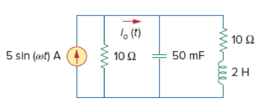
Figure 9.47
(a)
Find the value of the current
Answer to Problem 40P
The value of the current
Explanation of Solution
Given data:
Refer to Figure 9.47 in the textbook.
The value of the angular frequency
Formula used:
Write the expression to calculate the impedance of the passive elements resistor, inductor and capacitor.
Here,
Calculation:
The given circuit is redrawn as Figure 1.
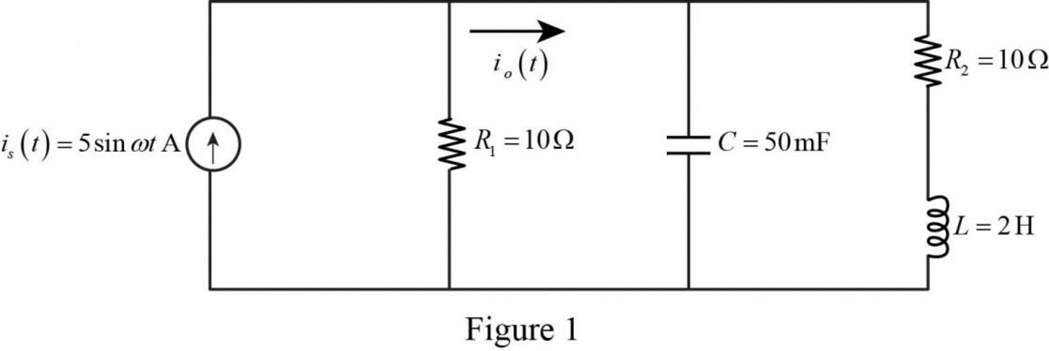
Refer to Figure 1, the current equation is,
Convert the given current into phasor form.
Substitute
Substitute
Substitute
Substitute
The Figure 1 is redrawn as impedance circuit in the following Figure 2.
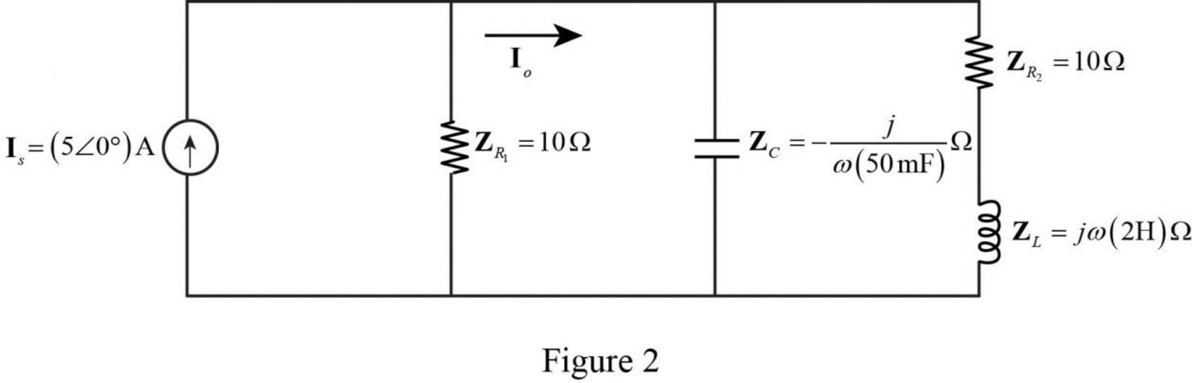
Write the expression to obtain the source transformation from current to voltage.
Substitute
Based upon the source transformation, the Figure 2 is reduced as the following Figure3.
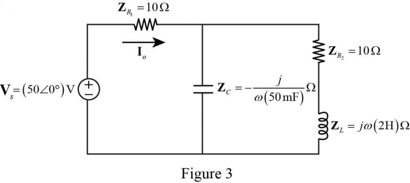
Refer to Figure 3, the series connected impedances
Therefore, the total equivalent impedance is calculated as follows.
Substitute
Substitute
Substitute
The reduced circuit of Figure 3 is drawn as Figure 4.
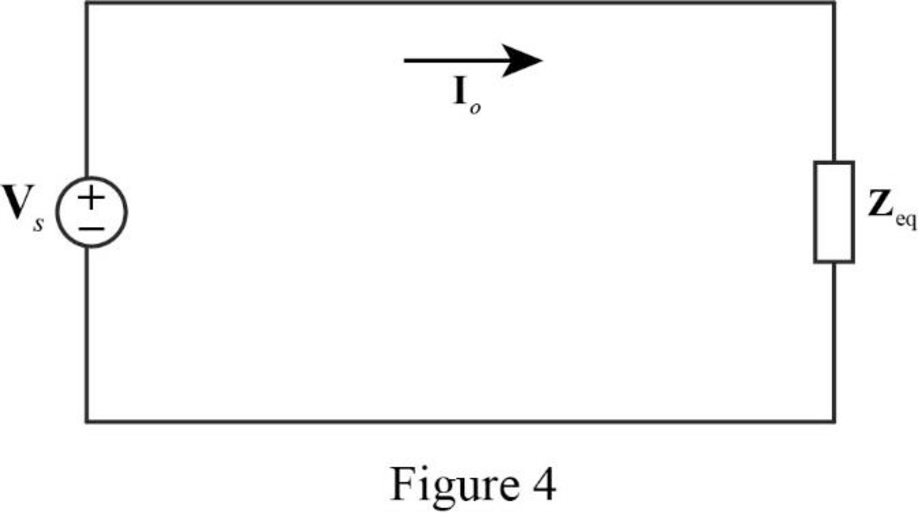
Refer to Figure 4, the current
Substitute
Convert the above equation from phasor form to time domain form.
Substitute
Conclusion:
Thus, the value of the current
(b)
Find the value of the current
Answer to Problem 40P
The value of the current
Explanation of Solution
Given data:
The value of the angular frequency
Calculation:
Substitute
Substitute
Substitute
Refer to Figure 4, the current
Substitute
Convert the above equation from phasor form to time domain form.
Substitute
Conclusion:
Thus, the value of the current
(c)
Find the value of the current
Answer to Problem 40P
The value of the current
Explanation of Solution
Given data:
The value of the angular frequency
Calculation:
Substitute
Substitute
Substitute
Refer to Figure 4, the current
Substitute
Convert the above equation from phasor form to time domain form.
Substitute
Conclusion:
Thus, the value of the current
Want to see more full solutions like this?
Chapter 9 Solutions
Fundamentals of Electric Circuits


- The current in an L-R-C series circuit has amplitude 0.120 Aand angular frequency 8.00 * 103 rad/s, and it has its maximum positivevalue at t = 0. The resistance is 95.0 Ω, the inductance is 6.50 mH,and the capacitance is 0.440 mF. For the resistor, inductor, and capacitor,find (a) the voltage amplitudes and (b) the instantaneous voltages att = 0.305 ms.arrow_forwardFind the impedance theoretically of a wire if it carries the frequency 10 kHz have a voltage is 8v, the current is 2mA, resistance is 12 kΩ , inductance 27 mH and capacitance 0.2 µfarrow_forward١** series RLC, R= 1 ohm, C= 0.2 F, L = 0.4H, Vs(t) = 10 Cos ( 5t - 45) V, the value of the capacitor complex power is?arrow_forward
- Assume that the voltage drop across the resistor, ER, is 78 V, that the voltage drop across the inductor, EL, is 104 V, and the circuit has a total impedance, Z, of 20 . The frequency of the AC voltage is 60 Hz. ETITZ20VAPFER78VIRRPEL104VILXLVARsLLarrow_forwardAssume that the voltage drop across the resistor, ER, is 78 V; the voltage drop across the capacitor, EC, is 104 V; and the circuit has a total impedance, Z, of 20 . The frequency of the AC voltage is 60 Hz. Find the missing values. ET ER78V EC104V IT IR IC Z20 R XC VA P VARSC PF Carrow_forward1. A source voltage of an AC series RLC circuit is 120 V. The circuit consists of the ff. quantities: R = 20 Ω, XL = 40 Ω, and XC = 40 Ω. The circuit current (in amperes) is Blank 1. 2. A 9 µF capacitor is in parallel with 3 µF capacitor. If the parallel capacitors is in series with an 8 µF capacitor, the value of total capacitance of the series-parallel connected capacitors is Blank 1.arrow_forward
- What is the magnitude of the impedance Z between nodes A and B with a resistance of R, a capacitance of C, and an inductance of L with the following values: ω = 3900 rad/s, R = 50 Ω, L=2.0×10^−8 H, C = 12 μF.arrow_forwardA resistor of 100 Ω, a coil of 4.50 μH, and a capacitor of 220 pF are in parallel. What is the admittance vector at 6.50 MHz? Provide illustration of the circuit.arrow_forwardA coil with impedance 8+j6 Ω is connected in series with a capacitive reactance X. The series combination is connected in parallel with a resistor R. Given that the equivalent impedance of the resulting circuit is 2.5∠0°Ω, find the value of X and R.arrow_forward
- An L-R-C series circuit has R = 60.0 Ω, L = 0.800 H, and C = 3.00 x 10⁻⁴ F. The ac source has voltage amplitude 90.0 V and angular frequency 120 rad/s. (a) What is the maximum energy stored in the inductor? (b) When the energy stored in the inductor is a maximum, how much energy is stored in the capacitor? (c) What is the maximum energy stored in the capacitor?arrow_forwardSolve by Routh,array test. Gp= 1/(S^3+3S^2+3s+1),Gc=Kc,Gm=1arrow_forwardDraw the root locus of the system given in the figure for K > 0.arrow_forward
 Delmar's Standard Textbook Of ElectricityElectrical EngineeringISBN:9781337900348Author:Stephen L. HermanPublisher:Cengage Learning