Fundamentals of Electric Circuits
6th Edition
ISBN: 9780078028229
Author: Charles K Alexander, Matthew Sadiku
Publisher: McGraw-Hill Education
bartleby

Videos

Textbook Question
Book Icon
Chapter 9, Problem 67P

At ω = 103 rad/s, find the input admittance of each of the circuits in Fig. 9.74.
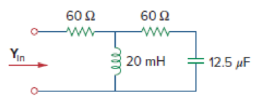
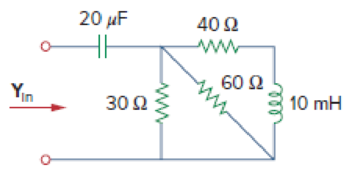
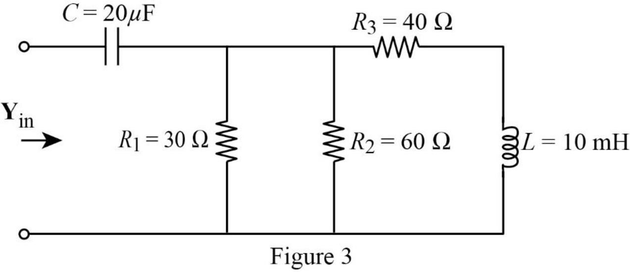
Chapter 9, Problem 67P, At  = 103 rad/s, find the input admittance of each of the circuits in Fig. 9.74. Figure 9.74 , example  1

Chapter 9, Problem 67P, At  = 103 rad/s, find the input admittance of each of the circuits in Fig. 9.74. Figure 9.74 , example  2

Figure 9.74

(a)

Expert Solution
Check Mark
To determine

Find the value of input admittance (Yin) for the circuit given in Figure 9.74(a).

Answer to Problem 67P

The value of input admittance (Yin) for the circuit given in Figure 9.74(a) is 14.820.22°mS.

Explanation of Solution

Given data:

Refer to Figure 9.74(a) in the textbook.

The value of angular frequency (ω) is 103rads.

Formula used:

Write a general expression to calculate the impedance of a resistor.

ZR=R        (1)

Here,

R is the value of resistance.

Write a general expression to calculate the impedance of an inductor.

ZL=jωL        (2)

Here,

L is the value of inductance, and

ω is the angular frequency.

Write a general expression to calculate the impedance of a capacitor.

ZC=1jωC        (3)

Here,

C is the value of capacitance.

Write a general expression to calculate the input admittance.

Yin=1Zin        (4)

Here,

Zin is the value of input impedance.

Calculation:

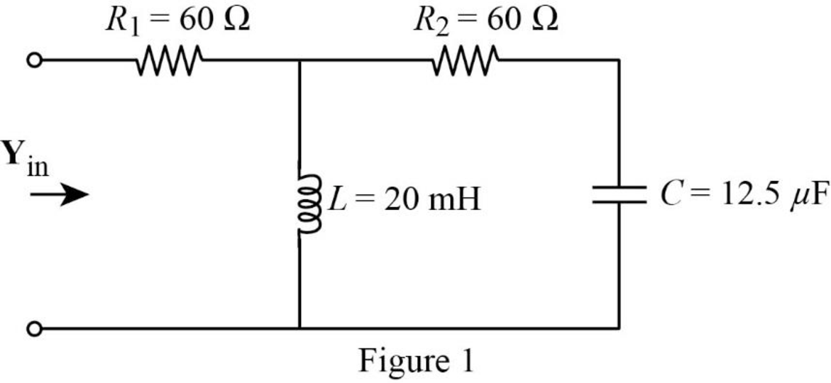
The given circuit is redrawn as shown in Figure 1.

Fundamentals of Electric Circuits, Chapter 9, Problem 67P , additional homework tip  1

Use equation (1) to find ZR1.

ZR1=60Ω

Use equation (1) to find ZR2.

ZR2=60Ω

Substitute 20mH for L, and 103rads for ω in equation (2) to find ZL.

ZL=j(103rads)(20mH)=j(103rads)(20×103Ωs){1m=1031H=1Ω1s}=j20Ω

Substitute 12.5μF for C, and 103rads for ω in equation (3) to find ZC.

ZC=1j(103rads)(12.5μF)=1j(103rads)(12.5×10⁶sΩ){1μ=1061F=1s1Ω}=j80Ω

The impedance diagram of Figure 1 is drawn as shown in Figure 2.

Fundamentals of Electric Circuits, Chapter 9, Problem 67P , additional homework tip  2

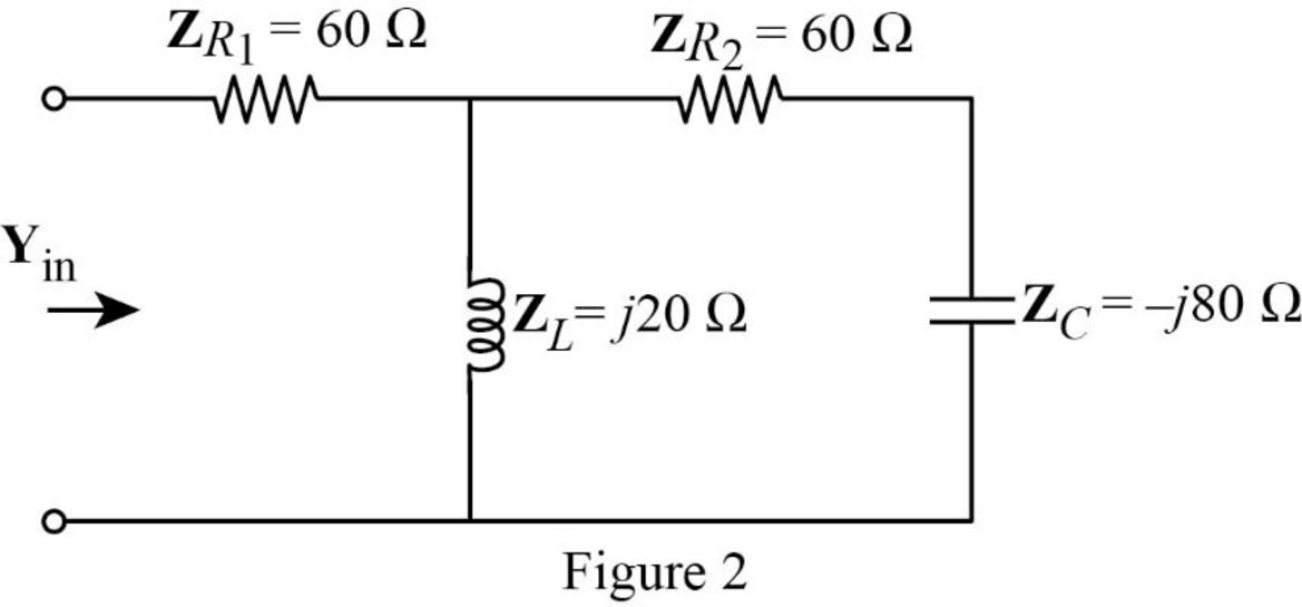
Refer to Figure 2, the impedance ZL  is connected in parallel with the series combination of the impedances ZR2 and ZC and this parallel combination is connected in series with the impedance ZR1.

The input impedance (Zin) is calculated as follows:

Zin=60Ω+(j20Ω(60j80)Ω)=60Ω+(j20Ω)(60j80)Ω(j20+60j80)Ω=60Ω+3.33Ω+j23.33Ω=(63.33+j23.33)Ω

Substitute 63.33Ω+j23.33Ω for Zin in equation (4) to find Yin.

Yin=1(63.33+j23.33)Ω=0.014820.22°S=14.8×10320.22°S=14.820.22°mS{1m=103}

Conclusion:

Thus, the value of input admittance (Yin) for the circuit given in Figure 9.74(a) is 14.820.22°mS.

(b)

Expert Solution
Check Mark
To determine

Find the value of input admittance (Yin) for the circuit given in Figure 9.74(b).

Answer to Problem 67P

The value of input admittance (Yin) for the circuit given in Figure 9.74(b) is 19.70474.56°mS.

Explanation of Solution

Calculation:

The given circuit is also redrawn as shown in Figure 3.

Fundamentals of Electric Circuits, Chapter 9, Problem 67P , additional homework tip  3

Use equation (1) to find ZR1.

 ZR1=30Ω

Use equation (1) to find ZR2.

ZR2=60Ω

Use equation (1) to find ZR3.

ZR3=40Ω

Substitute 10mH for L, and 103rads for ω in equation (2) to find ZL.

ZL=j(103rads)(10mH)=j(103rads)(10×103Ωs){1m=1031H=1Ω1s}=j10Ω

Substitute 20μF for C, and 103rads for ω in equation (3) to find ZC.

ZC=1j(103rads)(20μF)=1j(103rads)(20×106sΩ){1μ=1061F=1s1Ω}=j50Ω

The impedance diagram of Figure 3 is drawn as shown in Figure 4.

Fundamentals of Electric Circuits, Chapter 9, Problem 67P , additional homework tip  4

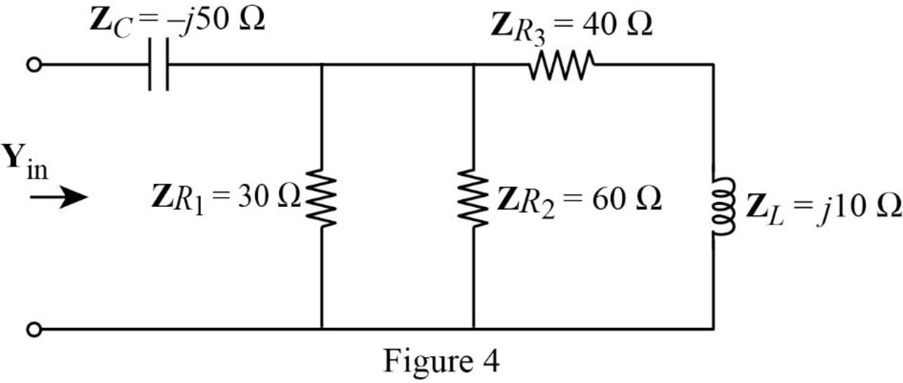
Refer to Figure 4, the impedances ZR1 and ZR2 are connected in parallel.

The equivalent impedance (Z1) is calculated as follows:

ZR=(30Ω)(60Ω)30Ω+60Ω=180Ω290Ω=20Ω

Now, the Figure 4 is reduced as shown in Figure 5.

Fundamentals of Electric Circuits, Chapter 9, Problem 67P , additional homework tip  5

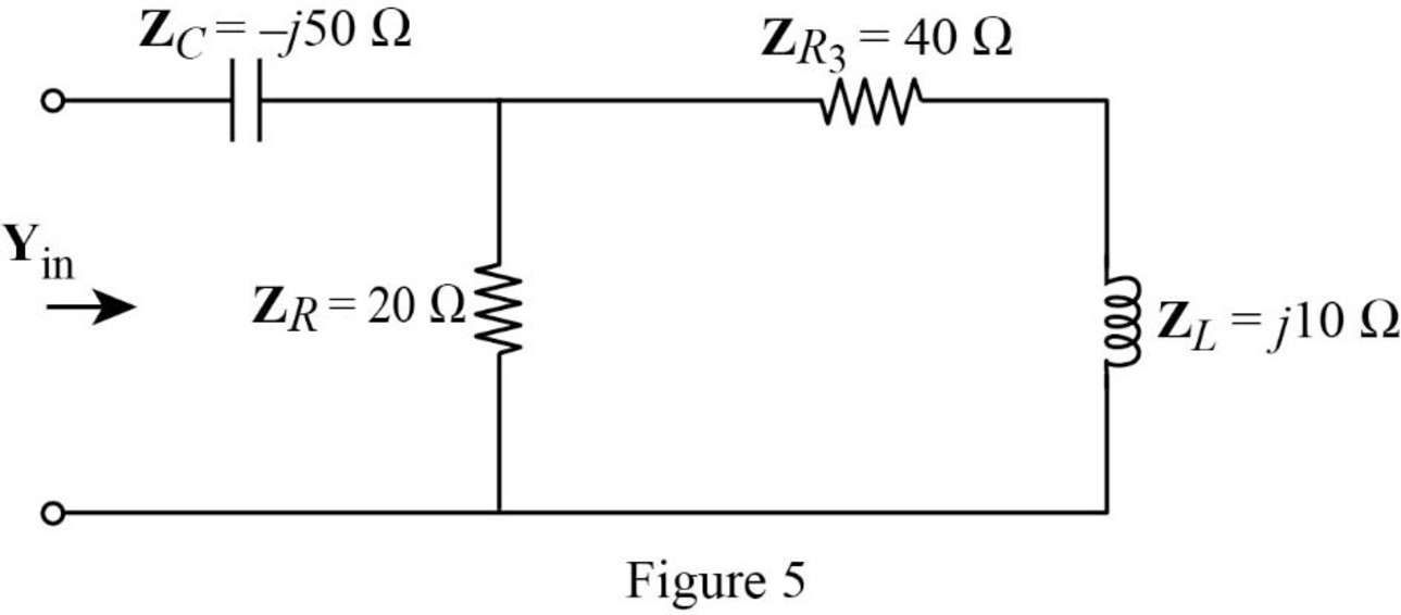
Refer to Figure 5, the impedance ZR is connected in parallel with the series combination of the impedances ZR3 and ZL and this parallel combination is connected in series with the impedance ZC.

The input impedance (Zin) is calculated as follows:

Zin=j50Ω+(20Ω(40+j10)Ω)=j50Ω+(20Ω)(40+j10)Ω(20+40+j10)Ω=j50Ω+13.51342Ω+j1.08109Ω=(13.51342Ωj48.9189)Ω

Substitute (13.51342Ωj48.9189)Ω for Zin in equation (4) to find Yin.

Yin=1(13.51342Ωj48.9189)Ω=0.01970474.56°S=19.704×10374.56°S=19.70474.56°mS{1m=103}

Conclusion:

Thus, the value of input admittance (Yin) for the circuit given in Figure 9.74(b) is 19.70474.56°mS.

Want to see more full solutions like this?

Subscribe now to access step-by-step solutions to millions of textbook problems written by subject matter experts!
Students have asked these similar questions
A series RLC AC circuit has R = 425 Ω, L =1.25 H, C = 3.50 µF, ω=377 s-1, and ΔVmax= 150 V.  (a) Determine the inductive reactance, the capacitive reactance, and the   impedance of the circuit.   Find both the maximum voltage and the instantaneous voltage across each element.
A given RLC circuit (Resistor-Inductor-Capacitor) has the following components: R = 4.1 Ohms L = 0.0099 H C = 0.00011 F If this system is driven by an oscillating current with frequency f = 2,594 Hz, what is the Inductive Reactance (XL) of this system?
The current in an L-R-C series circuit has amplitude 0.120 Aand angular frequency 8.00 * 103 rad/s, and it has its maximum positivevalue at t = 0. The resistance is 95.0 Ω, the inductance is 6.50 mH,and the capacitance is 0.440 mF. For the resistor, inductor, and capacitor,find (a) the voltage amplitudes and (b) the instantaneous voltages att = 0.305 ms.

Chapter 9 Solutions

Fundamentals of Electric Circuits

Ch. 9.7 - Calculate vo in the circuit of Fig. 9.27. Figure...Ch. 9.7 - Find I in the circuit of Fig. 9.30. Figure 9.30Ch. 9.8 - Design an RC circuit to provide a 90 lagging phase...Ch. 9.8 - Refer to the RL circuit in Fig. 9.36. If 10 V is...Ch. 9.8 - In the ac bridge circuit of Fig. 9.37, suppose...Ch. 9 - Which of the following is not a right way to...Ch. 9 - A function that repeats itself after fixed...Ch. 9 - Which of these frequencies has the shorter period?...Ch. 9 - If v1 = 30 sin(t + 10) and v2 = 20 sin(t + 50),...Ch. 9 - The voltage across an inductor leads the current...Ch. 9 - The imaginary part of impedance is called:...Ch. 9 - The impedance of a capacitor increases with...Ch. 9 - At what frequency will the output voltage v0(t) in...Ch. 9 - A series RC circuit has VR = 12 V and VC = 5 V....Ch. 9 - A series RCL circuit has R = 30 , XC = 50 , and XL...Ch. 9 - Given the sinusoidal voltage v(t) = 50 cos (30t +...Ch. 9 - A current source in a linear circuit has...Ch. 9 - Express the following functions in cosine form:...Ch. 9 - Design a problem to help other students better...Ch. 9 - Given v1=45sint+30V and v2=50cost30V, determine...Ch. 9 - For the following pairs of sinusoids, determine...Ch. 9 - If f() = cos + j sin , show that f() = ej.Ch. 9 - Calculate these complex numbers and express your...Ch. 9 - Evaluate the following complex numbers and leave...Ch. 9 - Design a problem to help other students better...Ch. 9 - Find the phasors corresponding to the following...Ch. 9 - Let X=440 and Y=2030. Evaluate the following...Ch. 9 - Evaluate the following complex numbers: (a)...Ch. 9 - Simplify the following expression: (a)...Ch. 9 - Evaluate these determinants: (a) 10+j62j351+j (b)...Ch. 9 - Prob. 16PCh. 9 - Two voltages v1 and v2 appear in series so that...Ch. 9 - Obtain the sinusoids corresponding to each of the...Ch. 9 - Using phasors, find: (a) 3cos20t+105cos20t30 (b)...Ch. 9 - A linear network has a current input 7.5cos10t+30A...Ch. 9 - Simplify the following: (a) ft=5cos2t+154sin2t30...Ch. 9 - An alternating voltage is given by v(t) = 55...Ch. 9 - Apply phasor analysis to evaluate the following:...Ch. 9 - Find v(t) in the following integrodifferential...Ch. 9 - Using phasors, determine i(t) in the following...Ch. 9 - Prob. 26PCh. 9 - A parallel RLC circuit has the node equation...Ch. 9 - Determine the current that flows through an 20-...Ch. 9 - Given that vc(0) = 2 cos(155) V, what is the...Ch. 9 - A voltage v(t) = 100 cos(60t + 20) V is applied to...Ch. 9 - A series RLC circuit has R = 80 , L = 240 mH, and...Ch. 9 - Using Fig. 9.40, design a problem to help other...Ch. 9 - A series RL circuit is connected to a 220-V ac...Ch. 9 - What value of will cause the forced response, vo...Ch. 9 - Find the steady-state current i in the circuit of...Ch. 9 - Using Fig. 9.43, design a problem to help other...Ch. 9 - Determine the admittance Y for the circuit in Fig....Ch. 9 - Using Fig. 9.45, design a problem to help other...Ch. 9 - For the circuit shown in Fig. 9.46, find Zeq and...Ch. 9 - In the circuit of Fig. 9.47, find io when: (a) =...Ch. 9 - Find v(t) in the RLC circuit of Fig. 9.48. Figure...Ch. 9 - Calculate vo(t) in the circuit of Fig. 9.49....Ch. 9 - Find current Io in the circuit shown in Fig. 9.50....Ch. 9 - Calculate i(t) in the circuit of Fig. 9.51. Figure...Ch. 9 - Find current Io in the network of Fig. 9.52....Ch. 9 - If vs = 100 sin(10t + 18) V in the circuit of Fig....Ch. 9 - In the circuit of Fig. 9.54, determine the value...Ch. 9 - Given that vs(t) = 20 sin (100t 40) in Fig. 9.55,...Ch. 9 - Find vs (t) in the circuit of Fig. 9.56 if the...Ch. 9 - Determine vx in the circuit of Fig. 9.57. Let...Ch. 9 - If the voltage vo across the 2- resistor in the...Ch. 9 - If V in the circuit of Fig. 9.59, find Is. Figure...Ch. 9 - Find Io in the circuit of Fig. 9.60.Ch. 9 - In the circuit of Fig. 9.61, Find Vs if Io=300A.Ch. 9 - Find Z in the network of Fig. 9.62, given that...Ch. 9 - At = 377 rad/s, find the input impedance of the...Ch. 9 - At = 1 rad/s, obtain the input admittance in the...Ch. 9 - Using Fig. 9.65, design a problem to help other...Ch. 9 - For the network in Fig. 9.66, find Zin. Let = 100...Ch. 9 - Obtain Zin for the circuit in Fig. 9.67. Figure...Ch. 9 - Find Zeq in the circuit in Fig. 9.68. Figure 9.68Ch. 9 - For the circuit in Fig. 9.69, find the input...Ch. 9 - For the circuit in Fig. 9.70, find the value of...Ch. 9 - Find ZT and Vo in the circuit in Fig. 9.71. Let...Ch. 9 - Determine ZT and I for the circuit in Fig. 9.72....Ch. 9 - For the circuit in Fig. 9.73, calculate ZT and...Ch. 9 - At = 103 rad/s, find the input admittance of each...Ch. 9 - Determine Yeq for the circuit in Fig. 9.75. Figure...Ch. 9 - Find the equivalent admittance Yeq of the circuit...Ch. 9 - Find the equivalent impedance of the circuit in...Ch. 9 - Obtain the equivalent impedance of the circuit in...Ch. 9 - Calculate the value of Zab in the network of Fig....Ch. 9 - Determine the equivalent impedance of the circuit...Ch. 9 - Design an RL circuit to provide a 90 leading phase...Ch. 9 - Design a circuit that will transform a sinusoidal...Ch. 9 - For the following pairs of signals, determine if...Ch. 9 - Refer to the RC circuit in Fig. 9.81. (a)...Ch. 9 - A coil with impedance 8 + j6 is connected in...Ch. 9 - (a) Calculate the phase shift of the circuit in...Ch. 9 - Consider the phase-shifting circuit in Fig. 9.83....Ch. 9 - The ac bridge in Fig. 9.37 is balanced when R1 =...Ch. 9 - A capacitance bridge balances when R1 = 100 , R2 =...Ch. 9 - An inductive bridge balances when R1 = 1.2 k, R2 =...Ch. 9 - The ac bridge shown in Fig. 9.84 is known as a...Ch. 9 - The ac bridge circuit of Fig. 9.85 is called a...Ch. 9 - The circuit shown in Fig. 9.86 is used in a...Ch. 9 - The network in Fig. 9.87 is part of the schematic...Ch. 9 - A series audio circuit is shown in Fig. 9.88. (a)...Ch. 9 - An industrial load is modeled as a series...Ch. 9 - An industrial coil is modeled as a series...Ch. 9 - Figure 9.91 shows a series combination of an...Ch. 9 - A transmission line has a series impedance of and...Ch. 9 - A power transmission system is modeled as shown in...
Knowledge Booster
Background pattern image
Electrical Engineering
Learn more about
Need a deep-dive on the concept behind this application? Look no further. Learn more about this topic, electrical-engineering and related others by exploring similar questions and additional content below.
Similar questions
SEE MORE QUESTIONS
Recommended textbooks for you
Text book image
Delmar's Standard Textbook Of Electricity
Electrical Engineering
ISBN:9781337900348
Author:Stephen L. Herman
Publisher:Cengage Learning
Y Parameters - Admittance Parameters; Author: Electrical Engineering Authority;https://www.youtube.com/watch?v=MLqqa8YbVrA;License: Standard Youtube License