
Videos
Find v(t) in the RLC circuit of Fig. 9.48.
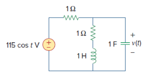
Figure 9.48
Find the value the voltage
Answer to Problem 41P
The value of the voltage
Explanation of Solution
Given date:
Refer to Figure 9.48 in the textbook.
Formula used:
Write the expression to convert the time domain expression into phasor domain.
Here,
A is the magnitude,
t is the time, and
Write the expression to calculate the total phasor current.
Here,
Write the expression to calculate the impedance of the passive elements resistor, inductor and capacitor.
Here,
Calculation:
The given RLC circuit is redrawn as Figure 1.
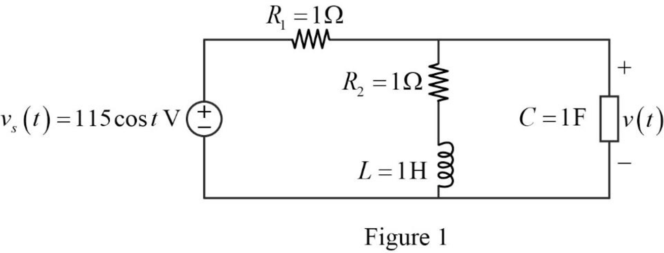
Refer to Figure 1, the source voltage is,
Here, angular frequency
Use the equation (1) to express the above equation in phasor form.
Substitute
Substitute
Substitute
Substitute
The Figure 1 is redrawn as impedance circuit in the following Figure 2.
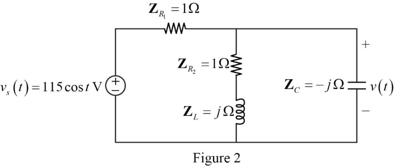
Refer to Figure 2, the series combination of the impedances
Write the expression to calculate the equivalent impedance 1 for the parallel combination as follows.
Here,
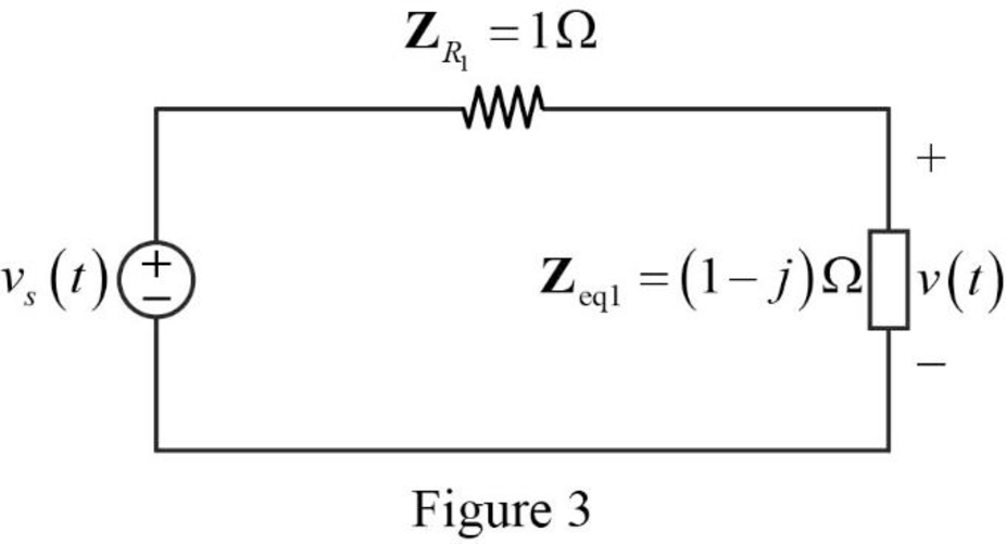
Substitute
The reduced circuit of the Figure 2 is drawn as Figure 3.
Refer to Figure 2, the impedances
Write the expression to calculate the equivalent capacitance for the series connected impedances
Here,
Substitute
The reduced circuit of the Figure 3 is drawn as Figure 4.
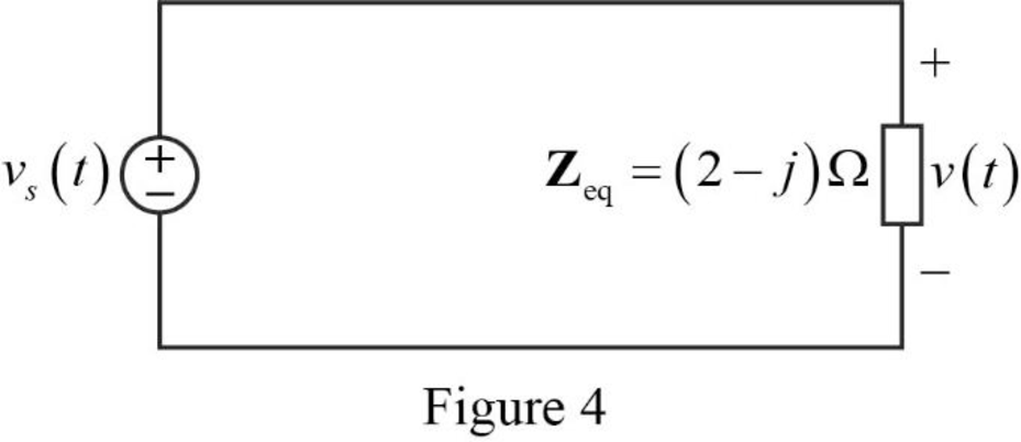
Substitute
Refer to Figure 2, the current through the capacitor is expressed as,
Refer to Figure 2, the voltage across the capacitor is expressed as,
Substitute
Substitute
Use the equation (1) to express the above equation in time domain form.
Substitute
Conclusion:
Thus, the value of the voltage
Want to see more full solutions like this?
Chapter 9 Solutions
Fundamentals of Electric Circuits
Additional Engineering Textbook Solutions
Electric machinery fundamentals
Microelectronics: Circuit Analysis and Design
Programmable Logic Controllers
Electrical Engineering: Principles & Applications (7th Edition)
Basic Engineering Circuit Analysis
Electric Circuits (10th Edition)


- d) Determine the phasors VL, VR and Vc.arrow_forwardA 250 pico-farad capacitance has a current drawing i = -12.75 cos(250t + 400) A. Determine the equation of voltage in the circuit.arrow_forwardA 160 μF capacitor is connected in series with a 10 Ω resistor. Write the equation of the current when the voltage is 220 Vp? a. 11.4 sin (377t + 59) b. 8.9 sin (377t – 46) c. 9.8 sin (377t + 52) d. 7.2 sin (377t + 46)arrow_forward
- A given RLC circuit (Resistor-Inductor-Capacitor) has the following components: R = 4.4 Ohms L = 0.0017 H C = 5.79 x10⁻⁶ F If this system is driven by an oscillating current with frequency f = 765 Hz, what is the Capacitive Reactance (XC) of this system?arrow_forward70. Ideal inductors and capacitors are 90 degrees out of phase with each other. True False 71. Ideal inductors and resistors are 180 degrees out of phase with each other. True False 72. Impedance of a circuit can be represented or expressed in complex form. True Falsearrow_forwardA given RLC circuit (Resistor-Inductor-Capacitor) has the following components: R = 4.1 Ohms L = 0.0099 H C = 0.00011 F If this system is driven by an oscillating current with frequency f = 2,594 Hz, what is the Inductive Reactance (XL) of this system?arrow_forward
- HELP ME THEVENIN’S THEOREM : calculate the Rth, Vth, and current at Zcarrow_forwardThe current in an L-R-C series circuit has amplitude 0.120 Aand angular frequency 8.00 * 103 rad/s, and it has its maximum positivevalue at t = 0. The resistance is 95.0 Ω, the inductance is 6.50 mH,and the capacitance is 0.440 mF. For the resistor, inductor, and capacitor,find (a) the voltage amplitudes and (b) the instantaneous voltages att = 0.305 ms.arrow_forward1. A source voltage of an AC series RLC circuit is 120 V. The circuit consists of the ff. quantities: R = 20 Ω, XL = 40 Ω, and XC = 40 Ω. The circuit current (in amperes) is Blank 1. 2. A 9 µF capacitor is in parallel with 3 µF capacitor. If the parallel capacitors is in series with an 8 µF capacitor, the value of total capacitance of the series-parallel connected capacitors is Blank 1.arrow_forward
- The voltage across a capacitor C is equal to v(t) = 8 cos(1000t) V. Determine the current i(t) through the capacitor at time t. C=100mu,F and t=8arrow_forwardThe equivalent phasor domain representation of the equation of the current i = 60 Sin (100πt - 30°) mA isarrow_forwardS:41) A circuit consists of a current source, Is = 43 sin(5386t - 40.29 °) mA in parallel with a 72 kΩ resistor and a 2895 pF capacitor. Determine the magnitude of the effective value of current that flows through the resistor.arrow_forward
 Delmar's Standard Textbook Of ElectricityElectrical EngineeringISBN:9781337900348Author:Stephen L. HermanPublisher:Cengage Learning