
Concept explainers
Videos
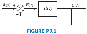
The unity feedback system shown in Figure P9.1 with
is operating with a dominant-pole damping ratio of 0.707. Design a PD controller so that the settling time is reduced by a factor of 2. Compare the transient and steady-state performance of the uncompensated and compensated systems. Describe any problems with your design. [Section: 9.3]
Want to see the full answer?
Check out a sample textbook solution
Chapter 9 Solutions
CONTROL SYSTEMS ENGINEERING


- 2.2 Please answer the best you can.arrow_forwardConsider the plant with transfer function G(s) connected in standard feedback configuration with the controller De(s) = K. 1) 2) = s+2 (s+1)²+1 Sketch the root locus for G(s). Explain what rules you used to plot it. (Be sure to describe the following: the number of branches, where they start and where they are going; the real-axis portion of the root locus; jw-axis crossings (if any); points of multiple roots (if any).) What conditions need to be imposed if we want our closed-loop system to have no oscillations under a step input? Explain the conditions from the root locus. + Ro Σ Dc(s) G(s) Figure 1: Control system in Problem 1.arrow_forwardPlease give some idea.arrow_forward
- If the system is to be arranged in a closed-loop, with a controller gain K in the forward path and a unity negative feedback loop, what is the maximum value of K which could be used without the system becoming unstable? Assuming you use Figure Q5 for this, use a sketch to show how you obtained the values from the plot.arrow_forward1. Give an example of open loop and closed loop system (one example each). Also state the input, control system, feedback and output parameter. Example. 1. Open Loop - Water Heater: Input - Water Temperature (Cold) System - Heating Element Output - Water Temperature (Hot) 2. Closed Loop - Air-conditioning System Input - Desired Room Temperature Control - Motor controller/Compressor/ACU Feedback - Temperature Sensing Output - Room Temperaturearrow_forwardThe open loop transfer function of a unity feedback control system is given below; G(s) = K s(s+2)(s2+2s+2) Plot the root locus and determine the value of k at the break away point.arrow_forward
- and 1) 2) LIUS S Consider the following feedback system, where K is a constant gain G(s) === 1 s3 +382 +s+1 Let K be a real number. Utilize the Routh-Hurwitz criterion to derive stability conditions for the closed-loop system. Suppose that the reference input r(t) = 1. What are the steady-state tracking errors (ess) for K = 1 and K = 3, respectively? R K G(s) Y Figure 2: Control system in Problem 2.arrow_forwardFigure Q2 shows the block diagram of a unity-feedback control system Proportional Controller Plant R(s) C(s). s(3s +1) 5+2s² +4 K 2.1- Determine the characteristic equation. 2.2- Using the Routh-Hurwitz criterion to determine the range of gain, K to ensure stability and marginally stability in the unity feedback syste m.arrow_forward1) Consider the system below: Vehicle Controller Steering dynamics Desired Actual bearing angle bearing angle 50 1 K s2 + 10s + 50 s(s + 5) Figure 1: Simplified Block Diagram of a Self-Guiding Vehicle's Bearing Angle Control. • Find a K value that the system has minimum rise time and minimum overshoot. Let us call this proportional gain as Kopt Show each step while finding Kopt- Show the necessary graphical solutions. Simulate the system response with 3 different K values. (Kopt and two other K values close to Kopt) Show the system response (actual bearing angle) in a single graph for different K values. • Comment on the results.arrow_forward
 Understanding Motor ControlsMechanical EngineeringISBN:9781337798686Author:Stephen L. HermanPublisher:Delmar Cengage Learning