Fundamentals of Electric Circuits
6th Edition
ISBN: 9780078028229
Author: Charles K Alexander, Matthew Sadiku
Publisher: McGraw-Hill Education
bartleby

Videos

Textbook Question
100%
Book Icon
Chapter 9, Problem 89CP

An industrial load is modeled as a series combination of an inductor and a resistance as shown in Fig. 9.89. Calculate the value of a capacitor C across the series combination so that the net impedance is resistive at a frequency of 2 kHz.
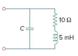
Chapter 9, Problem 89CP, An industrial load is modeled as a series combination of an inductor and a resistance as shown in

Figure 9.89

Expert Solution & Answer
Check Mark
To determine

Find the value of capacitor (C) when the net impedance is resistive at a frequency of 2kHz.

Answer to Problem 89CP

When the net impedance is resistive at a frequency of 2kHz, the value of capacitor (C) is 1.235μF.

Explanation of Solution

Given data:

Refer to Figure 9.89 in the textbook.

The value of frequency (f) is 2kHz.

Formula used:

Write a general expression to calculate the impedance of a resistor.

ZR=R        (1)

Here,

R is the value of resistance.

Write a general expression to calculate the impedance of an inductor.

ZL=jωL        (2)

Here,

L is the value of inductance, and

ω is the angular frequency.

Write a general expression to calculate the impedance of a capacitor.

ZC=1jωC        (3)

Here,

C is the value of capacitance.

Write a general formula to calculate the angular frequency.

ω=2πf        (4)

Here,

f is the value of frequency.

Calculation:

Refer to the given circuit, the value of resistor R is 10Ω and the value of inductor (L) is 5mH.

In the given circuit, the series of combination of resistor and inductor is connected in parallel with the capacitor.

The equivalent impedance of the given circuit is written as follows using equations (1), (2) and (3).

Zeq=1jωC(R+jωL)=1jωC(R+jωL)R+jωL+1jωC=(RjωC+LC)R+jωLj1ωC=(LCjRωC)R+j(ωL1ωC)

Simplify the above equation as follows:

Zeq=(LCjRωC)(Rj(ωL1ωC))R+j(ωL1ωC)(Rj(ωL1ωC))=(RLCjLC(ωL1ωC)jR2ωC+j2RωC(ωL1ωC))R2j2(ωL1ωC)2=(RLCjLC(ωL1ωC)jR2ωC+(1)RωC(ωL1ωC))R2(1)(ωL1ωC)2=(RLCjLC(ωL1ωC)jR2ωCRωC(ωL1ωC))R2+(ωL1ωC)2

Simplify the above equation as follows:

Zeq=(RLCjLC(ωL1ωC)jR2ωCRLC+Rω2C2)R2+(ωL1ωC)2=(Rω2C2jLC(ωL1ωC)jR2ωC)R2+(ωL1ωC)2

The equivalent impedance must be resistive when Im(Zeq)=0

Equate the imaginary part of above equation to zero.

LC(ωL1ωC)R2ωCR2+(ωL1ωC)2=0LC(ωL1ωC)R2ωC=0L(ωL1ωC)R2ω=0L(ωL1ωC)=R2ω

Simplify the above equation as follows:

ωL1ωC=R2ωL1ωC=ωL+R2ωL1ωC=ω2L2+R2ωL1C=ω(ω2L2+R2ωL)

Simplify the above equation to find C.

C=LR2+ω2L2        (5)

Substitute 2kHz for f in equation (4) to find ω.

ω=2π(2kHz)=2π(2×1031s){1k=1031Hz=1s}=12566rads

Substitute 10Ω for R, 12566rads for ω, and 5mH for L in equation (5) to find C.

C=5mH(10Ω)2+(12566rads)2(5mH)2=5×10³Ωs100Ω2+(1.58×10⁸rad2s2)(5×10³Ωs)2{1m=1031H=1Ω1s}=5×10³Ωs100Ω2+(1.58×10⁸rad2s2)(25×106Ω2s2)=5×10³Ωs100Ω2+3950Ω2

Simplify the above equation as follows:

C=5×10³Ωs4050Ω2=1.235×10⁶sΩ=1.235μF{1μ=1061F=1s1Ω}

Conclusion:

Thus, when the net impedance is resistive at a frequency of 2kHz, the value of capacitor (C) is 1.235μF.

Want to see more full solutions like this?

Subscribe now to access step-by-step solutions to millions of textbook problems written by subject matter experts!
Students have asked these similar questions
9. A capacitor has a resistance of 80ohms when connected to a 50 Hz supply. Calculate the value of capacitance A. 39.79 microfarad B. 39.97 microfarad C. 93.79 microfarad D. 93.97 microfarad
An inductor having an impedance of 6 + j8 is connected across a 200v supply.   The real       power supplied to it is              watts.        choices:      4000               3200                2400                1200
A 6.36 μF capacitor is connected in parallel with a resistance of 500Ω and the combination is connected in series with a 500Ω resistor. The whole circuit is connected across an ac source given by e=300sin(ωt) + 100 sin(3ωt + 30°). If ω = 314 rad/s. find: a)Irms b)Vrms c)total active power d)total power factor e)total reactive power f)total apparent power

Chapter 9 Solutions

Fundamentals of Electric Circuits

Ch. 9.7 - Calculate vo in the circuit of Fig. 9.27. Figure...Ch. 9.7 - Find I in the circuit of Fig. 9.30. Figure 9.30Ch. 9.8 - Design an RC circuit to provide a 90 lagging phase...Ch. 9.8 - Refer to the RL circuit in Fig. 9.36. If 10 V is...Ch. 9.8 - In the ac bridge circuit of Fig. 9.37, suppose...Ch. 9 - Which of the following is not a right way to...Ch. 9 - A function that repeats itself after fixed...Ch. 9 - Which of these frequencies has the shorter period?...Ch. 9 - If v1 = 30 sin(t + 10) and v2 = 20 sin(t + 50),...Ch. 9 - The voltage across an inductor leads the current...Ch. 9 - The imaginary part of impedance is called:...Ch. 9 - The impedance of a capacitor increases with...Ch. 9 - At what frequency will the output voltage v0(t) in...Ch. 9 - A series RC circuit has VR = 12 V and VC = 5 V....Ch. 9 - A series RCL circuit has R = 30 , XC = 50 , and XL...Ch. 9 - Given the sinusoidal voltage v(t) = 50 cos (30t +...Ch. 9 - A current source in a linear circuit has...Ch. 9 - Express the following functions in cosine form:...Ch. 9 - Design a problem to help other students better...Ch. 9 - Given v1=45sint+30V and v2=50cost30V, determine...Ch. 9 - For the following pairs of sinusoids, determine...Ch. 9 - If f() = cos + j sin , show that f() = ej.Ch. 9 - Calculate these complex numbers and express your...Ch. 9 - Evaluate the following complex numbers and leave...Ch. 9 - Design a problem to help other students better...Ch. 9 - Find the phasors corresponding to the following...Ch. 9 - Let X=440 and Y=2030. Evaluate the following...Ch. 9 - Evaluate the following complex numbers: (a)...Ch. 9 - Simplify the following expression: (a)...Ch. 9 - Evaluate these determinants: (a) 10+j62j351+j (b)...Ch. 9 - Prob. 16PCh. 9 - Two voltages v1 and v2 appear in series so that...Ch. 9 - Obtain the sinusoids corresponding to each of the...Ch. 9 - Using phasors, find: (a) 3cos20t+105cos20t30 (b)...Ch. 9 - A linear network has a current input 7.5cos10t+30A...Ch. 9 - Simplify the following: (a) ft=5cos2t+154sin2t30...Ch. 9 - An alternating voltage is given by v(t) = 55...Ch. 9 - Apply phasor analysis to evaluate the following:...Ch. 9 - Find v(t) in the following integrodifferential...Ch. 9 - Using phasors, determine i(t) in the following...Ch. 9 - Prob. 26PCh. 9 - A parallel RLC circuit has the node equation...Ch. 9 - Determine the current that flows through an 20-...Ch. 9 - Given that vc(0) = 2 cos(155) V, what is the...Ch. 9 - A voltage v(t) = 100 cos(60t + 20) V is applied to...Ch. 9 - A series RLC circuit has R = 80 , L = 240 mH, and...Ch. 9 - Using Fig. 9.40, design a problem to help other...Ch. 9 - A series RL circuit is connected to a 220-V ac...Ch. 9 - What value of will cause the forced response, vo...Ch. 9 - Find the steady-state current i in the circuit of...Ch. 9 - Using Fig. 9.43, design a problem to help other...Ch. 9 - Determine the admittance Y for the circuit in Fig....Ch. 9 - Using Fig. 9.45, design a problem to help other...Ch. 9 - For the circuit shown in Fig. 9.46, find Zeq and...Ch. 9 - In the circuit of Fig. 9.47, find io when: (a) =...Ch. 9 - Find v(t) in the RLC circuit of Fig. 9.48. Figure...Ch. 9 - Calculate vo(t) in the circuit of Fig. 9.49....Ch. 9 - Find current Io in the circuit shown in Fig. 9.50....Ch. 9 - Calculate i(t) in the circuit of Fig. 9.51. Figure...Ch. 9 - Find current Io in the network of Fig. 9.52....Ch. 9 - If vs = 100 sin(10t + 18) V in the circuit of Fig....Ch. 9 - In the circuit of Fig. 9.54, determine the value...Ch. 9 - Given that vs(t) = 20 sin (100t 40) in Fig. 9.55,...Ch. 9 - Find vs (t) in the circuit of Fig. 9.56 if the...Ch. 9 - Determine vx in the circuit of Fig. 9.57. Let...Ch. 9 - If the voltage vo across the 2- resistor in the...Ch. 9 - If V in the circuit of Fig. 9.59, find Is. Figure...Ch. 9 - Find Io in the circuit of Fig. 9.60.Ch. 9 - In the circuit of Fig. 9.61, Find Vs if Io=300A.Ch. 9 - Find Z in the network of Fig. 9.62, given that...Ch. 9 - At = 377 rad/s, find the input impedance of the...Ch. 9 - At = 1 rad/s, obtain the input admittance in the...Ch. 9 - Using Fig. 9.65, design a problem to help other...Ch. 9 - For the network in Fig. 9.66, find Zin. Let = 100...Ch. 9 - Obtain Zin for the circuit in Fig. 9.67. Figure...Ch. 9 - Find Zeq in the circuit in Fig. 9.68. Figure 9.68Ch. 9 - For the circuit in Fig. 9.69, find the input...Ch. 9 - For the circuit in Fig. 9.70, find the value of...Ch. 9 - Find ZT and Vo in the circuit in Fig. 9.71. Let...Ch. 9 - Determine ZT and I for the circuit in Fig. 9.72....Ch. 9 - For the circuit in Fig. 9.73, calculate ZT and...Ch. 9 - At = 103 rad/s, find the input admittance of each...Ch. 9 - Determine Yeq for the circuit in Fig. 9.75. Figure...Ch. 9 - Find the equivalent admittance Yeq of the circuit...Ch. 9 - Find the equivalent impedance of the circuit in...Ch. 9 - Obtain the equivalent impedance of the circuit in...Ch. 9 - Calculate the value of Zab in the network of Fig....Ch. 9 - Determine the equivalent impedance of the circuit...Ch. 9 - Design an RL circuit to provide a 90 leading phase...Ch. 9 - Design a circuit that will transform a sinusoidal...Ch. 9 - For the following pairs of signals, determine if...Ch. 9 - Refer to the RC circuit in Fig. 9.81. (a)...Ch. 9 - A coil with impedance 8 + j6 is connected in...Ch. 9 - (a) Calculate the phase shift of the circuit in...Ch. 9 - Consider the phase-shifting circuit in Fig. 9.83....Ch. 9 - The ac bridge in Fig. 9.37 is balanced when R1 =...Ch. 9 - A capacitance bridge balances when R1 = 100 , R2 =...Ch. 9 - An inductive bridge balances when R1 = 1.2 k, R2 =...Ch. 9 - The ac bridge shown in Fig. 9.84 is known as a...Ch. 9 - The ac bridge circuit of Fig. 9.85 is called a...Ch. 9 - The circuit shown in Fig. 9.86 is used in a...Ch. 9 - The network in Fig. 9.87 is part of the schematic...Ch. 9 - A series audio circuit is shown in Fig. 9.88. (a)...Ch. 9 - An industrial load is modeled as a series...Ch. 9 - An industrial coil is modeled as a series...Ch. 9 - Figure 9.91 shows a series combination of an...Ch. 9 - A transmission line has a series impedance of and...Ch. 9 - A power transmission system is modeled as shown in...
Knowledge Booster
Background pattern image
Electrical Engineering
Learn more about
Need a deep-dive on the concept behind this application? Look no further. Learn more about this topic, electrical-engineering and related others by exploring similar questions and additional content below.
Similar questions
SEE MORE QUESTIONS
Recommended textbooks for you
Text book image
Delmar's Standard Textbook Of Electricity
Electrical Engineering
ISBN:9781337900348
Author:Stephen L. Herman
Publisher:Cengage Learning
Y Parameters - Admittance Parameters; Author: Electrical Engineering Authority;https://www.youtube.com/watch?v=MLqqa8YbVrA;License: Standard Youtube License