
Videos
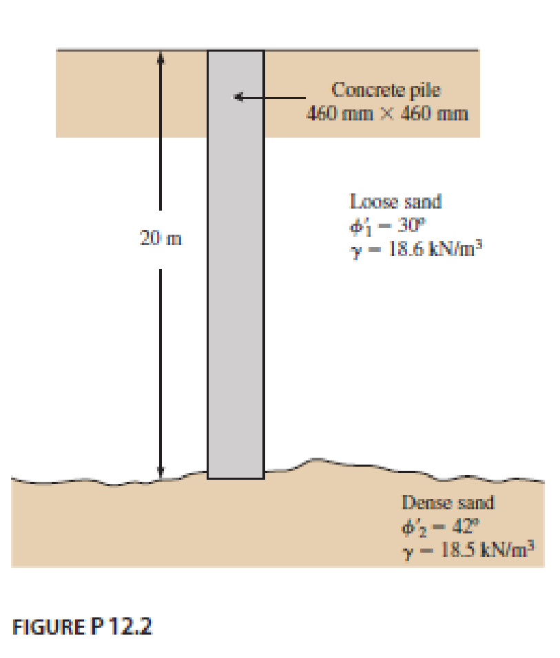
A 20 m long concrete pile is shown in Figure P12.2. Estimate the ultimate point load Qp by
- a. Meyerhof’s method
- b. Vesic’s method
- c. Coyle and Castello’s method
Use m = 600 in Eq. (12.28).
a.
Find the ultimate point load using Meyerhof’s method.
Answer to Problem 9.1P
The ultimate point load using Meyerhof’s method is
Explanation of Solution
Given information:
The length of the concrete pile is 20 m.
Area of the concrete pile
Soil friction angle
Unit weight of sand
Depth
Calculation:
Find the bearing capacity
Substitute 20 m for D and
Refer Table 12.6. “Interpolated values of
The value of
Take the atmospheric pressure
Find the value of ultimate point load
Here,
Find the value of
Substitute
Find the value of
Substitute
Substitute
The ultimate load should satisfy,
Substitute
So take the value of
Therefore, the ultimate point load using Meyerhof’s method is
b.
Find the ultimate point load using Vesic’s method.
Answer to Problem 9.1P
The ultimate point load using Vesic’s method is
Explanation of Solution
Calculation:
Find the modulus of elasticity
Substitute 600 for m and
Find the Poisson’s ratio of the soil using the relation:
Substitute 42 for
Find the value of average volumetric strain in the plastic zone below the pile point
Substitute 42 for
Find the value of rigidity index
Substitute
Find the value of reduced rigidity index
Substitute 66.1 for
Find the mean effective normal ground stress
Substitute
Refer Table 12.8. “Bearing capacity factors
The value of
Find the value of ultimate point load
Substitute
Therefore, the ultimate point load using Vesic’s method is
c.
Find the ultimate point load using Coyle and Castello’s method.
Answer to Problem 9.1P
The ultimate point load using Coyle and Castello’s is
Explanation of Solution
Calculation:
Find the value of
Substitute 20 m for L and 460 mm for D.
Refer Figure 12.20, “Variation of
The value of
Find the value of ultimate point load
Substitute
Therefore, the ultimate point load using Coyle and Castello’s method is
Want to see more full solutions like this?
Chapter 9 Solutions
Principles of Foundation Engineering (MindTap Course List)


- Refer to the pile shown in Figure P9.1. Estimate the side resistance Qs by Using Eqs. (9.40) through (9.42). Use K = 1.5 and Coyle and Castello’s method [Eq. (9.44)]arrow_forwardRefer to Figure 18.23. Given L1=3m, L2=6m, l1=1.5m, =16.5kN/m3, sat=19.0kN/m3 and =35. a. Find the required depth of the sheet pile, increasing the theoretical estimate by 30%. b. Determine the force in the tie rods if they are spaced 3 m apart horizontally. c. Find the maximum bending moment in the sheet pile.arrow_forwardA 600 mm diameter and 25 m long driven concrete pile carries a column load of 1200 kN. It is estimated that the shaft carries 900 kN and the point carries 300 kN. Determine the settlement of the pile head using the Poulos and Davis method with the following data: Es = 25 MN/m2, Ep = 30,000 MN/m2, and s = 0.2arrow_forward
- Determine the maximum load that can be allowed on a 450 mm diameter driven pile shown in Figure P12.6, allowing a factor of safety of 3. Use K = 1.5 Ko and = 0.65 in computing the shaft load. Use Meyerhofs method for computing the point load.arrow_forwardIn Problem 18.4, find the maximum bending moment in the sheet pile and determine the required section modulus, assuming an allowable stress of 190 MN/m2. 18.4 Refer to Figure 18.13. Given L1 = 1.5 m, L2 = 3 m; for the sand, =33, =16.5kN/m3, sat=19.0kN/m3; and, for the clay, c=50kN/m2, =0, sat=20kN/m3. Determine the depth of sheet pile required, allowing for a 50% increase from the theoretical estimate.arrow_forwardFigure 18.26a shows a pile. Let L = 20 m, D = 450 mm. Hf = 4m, f = 17.5 kN/m3, fill = 25. Determine the total downward drag force on the pile. Assume that the fill is located above the water table and that = 0.5 fill. FIG. 18.26 Negative skin frictionarrow_forward
- Refer to the pile shown in Figure P 9.1. Estimate the side resistance Qs bya. Using Eqs. (9.40) through (9.42). Use K = 1.5 and ẟ' = 0.6 Φ'b. Coyle and Castello’s method [Eq. (9.44)]arrow_forwardA 600 mm diameter and 25 m long driven concrete pile carries a column load of 1200 kN. It is estimated that the shaft carries 900 kN and the point carries 300 kN. Determine the settlement of the pile head using the Poulos and Davis method with the following data: Es = 25 MN/m2, Ep = 30,000 MN/m2 and ?s = 0.2.arrow_forwardRefer to Figure 18.9. A cantilever sheet pile is driven into a granular soil where the water table is 2 m (L1) below the top of the sand. The properties of the sand are =40, =17.5kN/m3, and sat=19kN/m3. It is proposed to excavate to a depth of 6 m (L) below the ground level. Determine the actual depth to which the sheet pile must be driven (L + D), using the net lateral pressure diagram. Note: Dactual=1.3(L3+L4)theoryarrow_forward
- Determine the maximum load that can be allowed on the 450 mm diameter pile shown in Figure P12.9, with a factor of safety of 3. Use the α method and Table 12.11 for determining the skin friction and Eq. (12.20) for determining the point load.arrow_forwardA 20-m-long concrete pile is shown in Figure P9.1. Estimate the ultimate point load Qp bya. Meyerhof’s methodb. Vesic’s methodc. Coyle and Castello’s methodUse m = 600 in Eq. (9.26).arrow_forwardFollowing is the variation of N60 with depth in a granular soil deposit. A concrete pile 9 m long (460 mm x 460 mm in cross section) is driven into the sand and fully embedded in the sand. Estimate the allowable load-carrying capacity of the pile (Qall). Use FS = 4 and Meyerhof’s equationsarrow_forward
 Principles of Foundation Engineering (MindTap Cou...Civil EngineeringISBN:9781337705028Author:Braja M. Das, Nagaratnam SivakuganPublisher:Cengage Learning
 Principles of Foundation Engineering (MindTap Cou...Civil EngineeringISBN:9781305081550Author:Braja M. DasPublisher:Cengage Learning
 Fundamentals of Geotechnical Engineering (MindTap...Civil EngineeringISBN:9781305635180Author:Braja M. Das, Nagaratnam SivakuganPublisher:Cengage Learning