
Principles of Foundation Engineering (MindTap Course List)
8th Edition
ISBN: 9781305081550
Author: Braja M. Das
Publisher: Cengage Learning
expand_more
expand_more
format_list_bulleted
Videos
Textbook Question
Chapter 9, Problem 9.4P
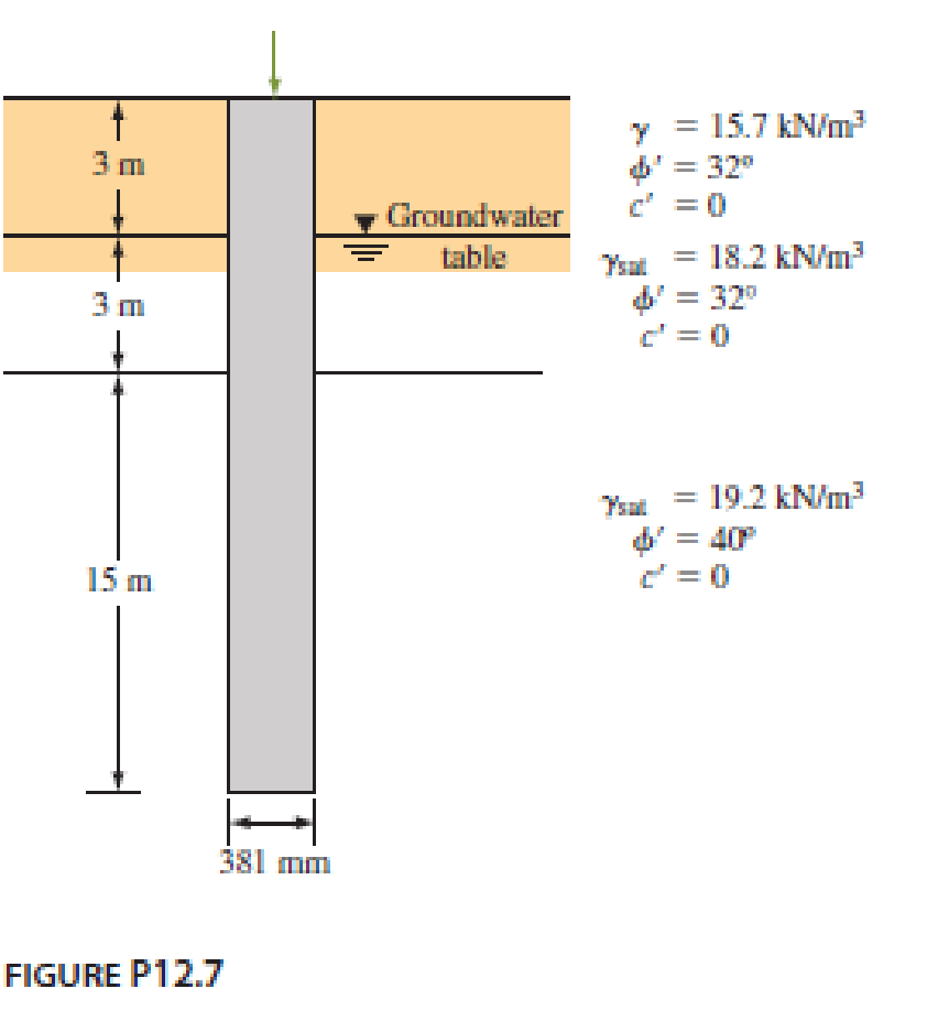
A driven closed-ended pile, circular in cross section, is shown in Figure P12.7. Calculate the following.
- a. The ultimate point load using Meyerhof’s procedure.
- b. The ultimate point load using Vesic’s procedure. Take Irr = 50.
- c. An approximate ultimate point load on the basis of parts (a) and (b).
- d. The ultimate frictional resistance Qs. [Use Eqs. (12.42) through (12.44), and take K = 1.4 and δ′ = 0.6ϕ′.]
- e. The allowable load of the pile (use FS = 4).
Expert Solution & Answer

Trending nowThis is a popular solution!

Students have asked these similar questions
Determine the ultimate load capacity of a circular pile with diameter D = 20 cm installed in asaturated soft clay. The pile is embedded 10 m into the ground. According to measurements, thesoil exhibits an undrained shear strength according to the linear relationship: Su = 2+1.6z, wherez is the depth in meters and Su is the undrained shear strength in kPa. The soil's unit weight canbe assumed as 18 kN/m3
The section of a 4 x 4 group pile in a layered saturated clay is shown in Figure P 9.29. The piles are square in cross section (356 mm x 356 mm). The center-to-center spacing (d) of the piles is 1 m. Determine the allowable load bearing capacity of the pile group. Use FS = 3 and Table 9.10.
Refer to the pile shown in Figure P 9.1. Estimate the side resistance Qs bya. Using Eqs. (9.40) through (9.42). Use K = 1.5 and ẟ' = 0.6 Φ'b. Coyle and Castello’s method [Eq. (9.44)]
Chapter 9 Solutions
Principles of Foundation Engineering (MindTap Course List)
Ch. 9 - A 20 m long concrete pile is shown in Figure...Ch. 9 - Refer to the pile shown in Figure P9.1. Estimate...Ch. 9 - Prob. 9.3PCh. 9 - A driven closed-ended pile, circular in cross...Ch. 9 - Prob. 9.5PCh. 9 - Prob. 9.6PCh. 9 - Prob. 9.7PCh. 9 - Prob. 9.8PCh. 9 - Prob. 9.9PCh. 9 - A concrete pile 16 in. 16 in. in cross section is...
Ch. 9 - Prob. 9.11PCh. 9 - Solve Problem 12.13 using Eqs. (12.59) and...Ch. 9 - Prob. 9.13PCh. 9 - Prob. 9.14PCh. 9 - A steel pile (H-section; HP 310 125; see Table...Ch. 9 - A concrete pile is 20 m long and has a cross...Ch. 9 - Prob. 9.17PCh. 9 - Prob. 9.18PCh. 9 - Solve Problem 12.23 using the method of Broms....Ch. 9 - Prob. 9.20PCh. 9 - Solve Problem 12.25 using the modified EN formula....Ch. 9 - Solve Problem 12.25 using the modified Danish...Ch. 9 - Figure 12.49a shows a pile. Let L = 15 m, D (pile...Ch. 9 - Redo Problem 12.30 assuming that the water table...Ch. 9 - Refer to Figure 12.49b. Let L = 18 m, fill = 17...Ch. 9 - A concrete pile measuring 16 in. × 16 in. in cross...Ch. 9 - The plan of a group pile is shown in Figure...Ch. 9 - Prob. 9.28PCh. 9 - The section of a 4 × 4 group pile in a layered...Ch. 9 - Prob. 9.30P
Knowledge Booster


Learn more about
Need a deep-dive on the concept behind this application? Look no further. Learn more about this topic, civil-engineering and related others by exploring similar questions and additional content below.Similar questions
- A 600 mm diameter and 25 m long driven concrete pile carries a column load of 1200 kN. It is estimated that the shaft carries 900 kN and the point carries 300 kN. Determine the settlement of the pile head using the Poulos and Davis method with the following data: Es = 25 MN/m2, Ep = 30,000 MN/m2, and s = 0.2arrow_forwardFigure 18.26a shows a pile. Let L = 20 m, D = 450 mm. Hf = 4m, f = 17.5 kN/m3, fill = 25. Determine the total downward drag force on the pile. Assume that the fill is located above the water table and that = 0.5 fill. FIG. 18.26 Negative skin frictionarrow_forwardDetermine the maximum load that can be allowed on a 450 mm diameter driven pile shown in Figure P12.6, allowing a factor of safety of 3. Use K = 1.5 Ko and = 0.65 in computing the shaft load. Use Meyerhofs method for computing the point load.arrow_forward
- Redo Problem 12.20 using Vesics method, assuming that the skin friction is distributed uniformly along the shaft. 12.20 A 600 mm diameter and 25 m long driven concrete pile carries a column load of 1200 kN. It is estimated that the shaft carries 900 kN and the point carries 300 kN. Determine the settlement of the pile head using the Poulos and Davis method with the following data: Es = 25 MN/m2, Ep = 30,000 MN/m2, and s = 0.2arrow_forwardRefer to Figure 18.23. Given L1=3m, L2=6m, l1=1.5m, =16.5kN/m3, sat=19.0kN/m3 and =35. a. Find the required depth of the sheet pile, increasing the theoretical estimate by 30%. b. Determine the force in the tie rods if they are spaced 3 m apart horizontally. c. Find the maximum bending moment in the sheet pile.arrow_forwardA driven closed-ended pile, circular in cross section, is shown in Figure P 9.4.Calculate the following.a. The ultimate point load using Meyerhof’s procedure.b. The ultimate point load using Vesic’s procedure. Take Irr = 50.c. An approximate ultimate point load on the basis of parts (a) and (b).d. The ultimate frictional resistance Qs. [Use Eqs. (9.40 (L' ≈ 15 D)) through (9.42), and take K = 1.4 and ẟ' = 0.6 Φ'.]e. The allowable load of the pile (use FS = 4).arrow_forward
- A steel pile (H-section; HP 360 1.491; see Table 18.1) is driven into a layer of sandstone The length of the pile is 18.9 m. Following are the properties of the sandstone: Unconfined compression strength = qu(lab) = 78.7 MN/m2 Angle of friction = 36 Using a factor of safety of 3, estimate the allowable point load that can be carried by the pile. Use Eq. (18.42).arrow_forwardDetermine the maximum load that can be allowed on the 450 mm diameter pile shown in Figure 18.36, with a safety factor of 3. Use the a method for computing the shaft friction. FIG. 18.36arrow_forwardDetermine the maximum load that can be allowed on the 450 mm diameter pile shown in Figure P12.9, with a factor of safety of 3. Use the α method and Table 12.11 for determining the skin friction and Eq. (12.20) for determining the point load.arrow_forward
- A driven closed-ended pile, circular in cross section, is shown in Figure 1. Calculate the following. a. The ultimate point load using Meyerhof’s procedure. b. The ultimate point load using Vesic’s procedure. Take Irr = 50.arrow_forwardA 20-m-long concrete pile is shown in Figure P9.1. Estimate the ultimate point load Qp bya. Meyerhof’s methodb. Vesic’s methodc. Coyle and Castello’s methodUse m = 600 in Eq. (9.26).arrow_forward
arrow_back_ios
arrow_forward_ios
Recommended textbooks for you
 Fundamentals of Geotechnical Engineering (MindTap...Civil EngineeringISBN:9781305635180Author:Braja M. Das, Nagaratnam SivakuganPublisher:Cengage Learning
 Principles of Foundation Engineering (MindTap Cou...Civil EngineeringISBN:9781337705028Author:Braja M. Das, Nagaratnam SivakuganPublisher:Cengage Learning
 Principles of Foundation Engineering (MindTap Cou...Civil EngineeringISBN:9781305081550Author:Braja M. DasPublisher:Cengage Learning
Fundamentals of Geotechnical Engineering (MindTap...
Civil Engineering
ISBN:9781305635180
Author:Braja M. Das, Nagaratnam Sivakugan
Publisher:Cengage Learning
Principles of Foundation Engineering (MindTap Cou...
Civil Engineering
ISBN:9781337705028
Author:Braja M. Das, Nagaratnam Sivakugan
Publisher:Cengage Learning
Principles of Foundation Engineering (MindTap Cou...
Civil Engineering
ISBN:9781305081550
Author:Braja M. Das
Publisher:Cengage Learning
Concrete Slab Calculations 006; Author: Jerry Howard;https://www.youtube.com/watch?v=R19jILyBxio;License: Standard Youtube License