Concept explainers
Find the total stress
Answer to Problem 9.1P
The total stress at point A is
The pore water pressure at point A is
The effective stress at point A is
The total stress at point B is
The pore water pressure at point B is
The effective stress at point B is
The total stress at point C is
The pore water pressure at point C is
The effective stress at point C is
The total stress at point D is
The pore water pressure at point D is
The effective stress at point D is
Explanation of Solution
Given information:
The thickness
The thickness
The thickness
The dry unit weight
The saturated unit weight
The saturated unit weight
Calculation:
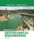
Calculate the total stress at point A (0 ft).
Thus, the total stress at point A is
Calculate the pore water pressure at point A (0 ft).
Thus, pore water pressure at point A is
Calculate the effective stress at point A (0 ft) using the relation.
Substitute 0 for
Thus, effective stress at point A is
Calculate the total stress at point B (7 ft) using the relation.
Substitute
Thus, total stress at point B is
Calculate the pore water at point B (7 ft) using the relation.
Thus, the pore water pressure at point B is
Calculate the effective stress at point B (7 ft) using the relation.
Substitute
Thus, the effective stress at point B is
Calculate the total stress at point C (19 ft) using the relation.
Substitute
Thus, the total stress at point C is
Calculate the pore water pressure at point C (19 ft) using the relation.
Here,
Take the unit weight of the water as
Substitute
Thus, the pore water pressure at point C is
Calculate the effective stress at point C (19 ft) using the relation.
Substitute
Thus, the effective stress at point C is
Calculate the total stress at point D (25 ft) using the relation.
Substitute
Thus, the total stress at point D is
Calculate the pore water pressure at point D (25 ft) using the relation.
Substitute
Thus, the pore water pressure at point D is
Calculate the effective stress at point D (25 ft) using the relation.
Substitute
Thus, the effective stress at point D is
Show the plot between depth and total stress as in Figure 1.
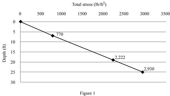
Show the plot between depth and pore water pressure as in Figure 2.
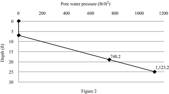
Show the plot between depth and effective stress as in Figure 3.
Want to see more full solutions like this?
Chapter 9 Solutions
EBK PRINCIPLES OF GEOTECHNICAL ENGINEER


- A 2 m Ya = 17 kN/m3 Layer 1 Groundwater table Practice Problem 2: A soil profile consisting of three layers is shown in Figure 1.6. Calculate the values of o, u, and o' at points A, B, C, and D. In each case, plot 1.5 m the variations of o, u, and ' with depth. 4 m Ysat = 18 kN/m3 Layer 2 Ysat= 20 kN/m2 Layer 3 O Dry sand Sand Clay Rock Figure 1.6arrow_forward7. A soil profile consisting of three layers is shown in the figure. Calculate the values of the total stress, effective stress ad pore water pressure at points A, B, C, and D for the following cases. In each case, plot the variations with depth. Characteristics of layers 1, 2, and 3 for each case are given below:arrow_forwardQ-1: A soil profile consisting of three layers is shown in the following figure. a) Calculate the values of o, u and o' at points A, B, C, and D Layer no. 1 2 3 ↑ H₁ H₂ H₂ Thickness H, = 2.1 m H₂ = 3.66 m H₂ = 1.83 m Dry sand Soll parameters Y₁ = 17.23 kN/m³ Ysat 18.96 kN/m³ Ysat 18.5 kN/m³ Sand Clay Rock Layer 1 Groundwater table Layer 2 Layer 3 ⒸDengage Learning 2014 b) Calculate the effective stress at c when water table drops by 2m (consider x 16.5 for layer 2). c) Calculate the effective stress at c when water table rises by 2m above layer 1 due to flooding (consider Ysa 18.5 for layer 1).arrow_forward
- Q2. A soil profile consisting of three layers is shown in Figure 1 below. Unit weight of water (yw) = 9.81 kN/m³ Layer no. 1 2 3 ↑ H₁ H₂ Dry sand Sand Clay Rock Figure 1: Soil Profile Thickness H₁ = 1.5 m H₂ = 2.53 m H3 = 2.64 m Layer 1 Groundwater table Layer 2 Layer 3 Soil parameters Yd = 16.5 kN/m³, Ysat = 17.42 kN/m³ Ya = 16.5 kN/m³, Ysat = 18.55 kN/m³ Yd = 17.50 kN/m³, Ysat = 19.23 kN/m³ a) Calculate the values of o, u and o' at points A, B, C and D. b) Calculate the effective stress at C when water table drops by 2 m. c) Calculate the effective stress at C when water table rises by 1 m above layer 1 due to flooding.arrow_forwardA soil profile consisting of three layers is shown in the below figure. Calculate the values of o, u, and o' at points A, B, C, and D for the following case:arrow_forwardA soil profile is shown in Figure P3.2 along with the standard penetration numbers in the clay layer. Use Eqs. (3.8) and (3.9) to determine the variation of cu and OCR with depth. What is the average value of cu and OCR?arrow_forward
- 7. A soil profile consisting of three layers is shown in the figure. Calculate the values of the total stress, effective stress ad pore water pressure at points A, B, C, and D for the following cases. In each case, plot the variations with depth. Characteristics of layers 1, 2, and 3 for each case are given below: Page 3 of 4 Layer 1 Groundwater table Layer 2 Layer 3 Dry sand Sand Clay Rock Layer no. Thickness Soil parameters 1 Y = 110 lb/ft³ 121 Ib/ft H = 7 ft 2 %3D Yat = 3 H, = 6 ft Yeat = 118 lb/ft³ e = 0.7; G, = 2.69 e = 0.55; G, = 2.7 w = 38%;e = 1.2 %3D 1 H = 5 m II, = 8 m %3D 3 H, = 3 m 1 H, = 3 m Y = 16 kN/m 18 kN/m 2 H¸ = 6 m Yat 3 H, = 2.5 m 17 kN/m %3D Ysat %3D 2.arrow_forward- Please Help!!arrow_forwardA soil profile consisting of three layers is shown below. Calculate the values of σ, μ, and σ’ at points A, B, C, and D.arrow_forward
- A soil profile is shown in Figure Q. Given: Layer I – H, = 3 m, Ya = 15 kN/m³; Layer II – H, = 4 m, Ysat = 16 kN/m³; Layer III – H3 = 5 m, Ysat = 18 kN/m³. Plot the variation of a, u and o' with depth. %3D A Layer I Groundwater table H2 Layer II H3 Layer III Figure Q : Dry sand Sand Clay Rockarrow_forwardQ.11 Consider the three layered soil strata shown in the figure below. The thickness and coefficient of vertical permeability of each layer is mentioned in the figure. Flow Ah = 0.50 m -3 H, = 3 m K, = 3 x 10° cm/s %3D -2 H2 = 2 m K, = 6.5 x 10 cm/s H = 9 m H3 = 4 m. L = 2 m -4 Kg = 7 x 10 cm/s The total head loss in three layers isarrow_forward: A soil profile consisting of three layers is shown in the following figure. a) Calculate the values of o, u and o' at points A, B, C, and D ayer no. Thickness Soll parameters H, = 2.1 m H2 = 3.66 m H; = 1.83 m Ya = 17.23 kN/m³ Yat = 18.96 kN/m³ Y = 18.5 kN/m 1 %3D 3 %3D Layer 1 B. Groundwater table H2 Layer 2 Layer 3 Dry sand Sand Clay Rock b) Calculate the effective stress at c when water table drops by 2m (consider Ya= 16.5 for layer 2). c) Calculate the effective stress at c when water table rises by 2m above layer 1 due to flooding (consider ysa- 18.5 for layer 1). O Cengage Learning 2014arrow_forward
 Fundamentals of Geotechnical Engineering (MindTap...Civil EngineeringISBN:9781305635180Author:Braja M. Das, Nagaratnam SivakuganPublisher:Cengage Learning