Mechanics of Materials, Student Value Edition Plus Mastering Engineering with Pearson eText -- Access Card Package (10th Edition)
10th Edition
ISBN: 9780134326054
Author: Russell C. Hibbeler
Publisher: PEARSON
expand_more
expand_more
format_list_bulleted
Concept explainers
Videos
Textbook Question
Chapter 9.3, Problem 9.23P
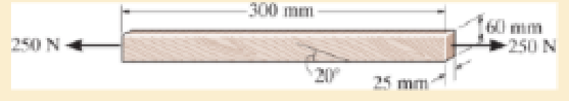
The grains of wood in the board make an angle of 20° with the horizontal as shown. Determine the normal and shear stress that act perpendicular and parallel to the grains if the board is subjected to an axial load of 250 N.
Expert Solution & Answer
Want to see the full answer?
Check out a sample textbook solution
Students have asked these similar questions
The grains of wood in the board make an angle of 20° with the horizontal as shown. Determine the normal and shear stresses that act perpendicular and parallel to the grains if the board is subjected to an axial load of 250 N.
The bar has a cross-sectional area of 0.5 in2 and is made of a material that has a stress-strain diagram that can be approximated by the two line segments. Determine the elongation of the bar due to the applied loading.
The distributed loading is applied to the rigid beam, which is supported by the three bars. Each bar has a cross-sectional area of 1.25 in2 and is made from a material having a stress–strain diagram that can be approximated bythe two line segments. If a load of w = 25 kip>ft is applied to the beam, determine the stress in each bar and the vertical displacement of the beam.
Chapter 9 Solutions
Mechanics of Materials, Student Value Edition Plus Mastering Engineering with Pearson eText -- Access Card Package (10th Edition)
Ch. 9.3 - In each case, the state of stress x, y, xy...Ch. 9.3 - Given the state of stress shown on the element,...Ch. 9.3 - Determine the normal stress and shear stress...Ch. 9.3 - Determine the equivalent state of stress on an...Ch. 9.3 - Also, find the corresponding orientation of the...Ch. 9.3 - Determine the equivalent state of stress on an...Ch. 9.3 - Determine the maximum principal stress at point B.Ch. 9.3 - Determine the principal stress at point C.Ch. 9.3 - Prove that the sum of the normal stresses x + y =...Ch. 9.3 - Determine the stress components acting on the...
Ch. 9.3 - Determine the stress components acting on the...Ch. 9.3 - Determine the normal stress and shear stress...Ch. 9.3 - Determine the normal stress and shear stress...Ch. 9.3 - Determine the stress components acting on the...Ch. 9.3 - Determine the stress components acting on the...Ch. 9.3 - Solve Prob.97 using the stress transformation...Ch. 9.3 - Determine the stress components acting on the...Ch. 9.3 - Solve Prob.99 using the stress transformation...Ch. 9.3 - Determine the equivalent state of stress on an...Ch. 9.3 - Determine the equivalent slate of stress on an...Ch. 9.3 - Determine the stress components acting on the...Ch. 9.3 - Determine (a) the principal stresses and (b) the...Ch. 9.3 - The state of stress at a point is shown on the...Ch. 9.3 - Determine the equivalent state of stress on an...Ch. 9.3 - Determine the equivalent state of stress on an...Ch. 9.3 - A point on a thin plate is subjected to the two...Ch. 9.3 - Determine the equivalent state of stress on an...Ch. 9.3 - The stress along two planes at a point is...Ch. 9.3 - The stress acting on two planes at a point is...Ch. 9.3 - The state of stress at a point in a member is...Ch. 9.3 - The grains of wood in the board make an angle of...Ch. 9.3 - The wood beam is subjected to a load of 12 kN. If...Ch. 9.3 - The internal loadings at a section of the beam are...Ch. 9.3 - Solve Prob.925 for point B. 925. The internal...Ch. 9.3 - Solve Prob.925 for point C. 925. The internal...Ch. 9.3 - It is subjected to a torque of 12 kip in. and a...Ch. 9.3 - The bell crank is pinned at A and supported by a...Ch. 9.3 - The beam has a rectangular cross section and is...Ch. 9.3 - A paper tube is formed by rolling a cardboard...Ch. 9.3 - Solve Prob.931 for the normal stress acting...Ch. 9.3 - The 2-in.-diameter drive shaft AB on the...Ch. 9.3 - Determine the principal stresses in the...Ch. 9.3 - The internal loadings at a cross section through...Ch. 9.3 - The internal loadings at a cross section through...Ch. 9.3 - The shaft has a diameter d and is subjected to the...Ch. 9.3 - The steel pipe has an inner diameter of 2.75 in....Ch. 9.3 - Solve Prob.938 for point B, w1ich is located on...Ch. 9.3 - The wide-flange beam is subjected to the 50-kN...Ch. 9.3 - Solve Pro b. 9-40 for point B located on the web...Ch. 9.3 - The box beam is subjected to the 26-kN force that...Ch. 9.3 - Solve Prob.942 for point B. 942. The box beam is...Ch. 9.4 - Use Mohrs circle to determine the normal stress...Ch. 9.4 - Also, find the corresponding orientation of the...Ch. 9.4 - Draw Mohrs circle and determine the principal...Ch. 9.4 - Determine the principal stresses at a point on the...Ch. 9.4 - Determine the principal stresses at point A on the...Ch. 9.4 - Point A is just below the flange.Ch. 9.4 - Solve Prob.9-2 using Mohrs circle. 92. Determine...Ch. 9.4 - Solve Prob.93 using Mohrs circle. 93. Determine...Ch. 9.4 - Solve Prob.96 using Mohrs circle. 96. Determine...Ch. 9.4 - Solve Prob.911 using Mohrs circle. 911. Determine...Ch. 9.4 - Solve Prob.915 using Mohrs circle. 915. The state...Ch. 9.4 - Solve Prob.916 using Mohrs circle. 916. Determine...Ch. 9.4 - Mohrs circle for the state of stress is shown in...Ch. 9.4 - Determine (a) the principal stresses and (b) the...Ch. 9.4 - Determine (a) the principal stresses and (b) the...Ch. 9.4 - Determine the equivalent state of stress if an...Ch. 9.4 - Draw Mohrs circle that describes each of the...Ch. 9.4 - Draw Mohrs circle trial describes each of the...Ch. 9.4 - Determine (a) the principal stresses and (b) the...Ch. 9.4 - Determine (a) the principal stresses and (b) the...Ch. 9.4 - Determine (a) the principal stresses and (b) the...Ch. 9.4 - Determine (a) the principal stresses and (b) the...Ch. 9.4 - Determine (a) the principal stresses and (b) the...Ch. 9.4 - Draw Mohrs circle that describes each of the...Ch. 9.4 - The grains of wood in the board make an angle of...Ch. 9.4 - The post is fixed supported at its base and a...Ch. 9.4 - Determine the principal stresses, the maximum...Ch. 9.4 - The thin-walled pipe has an inner diameter of 0.5...Ch. 9.4 - The frame supports the triangular distributed load...Ch. 9.4 - The frame supports the triangular distributed load...Ch. 9.4 - The rotor shaft of the helicopter is subjected to...Ch. 9.4 - The pedal crank for a bicycle has the cross...Ch. 9.4 - A spherical pressure vessel has an inner radius of...Ch. 9.4 - The cylindrical pressure vessel has an inner...Ch. 9.4 - Determine the normal and shear stresses at point D...Ch. 9.4 - Determine the principal stress at point D, Which...Ch. 9.4 - If the box wrench is subjected to the 50 lb force,...Ch. 9.4 - If the box wrench is subjected to the 50-lb force,...Ch. 9.4 - The post is fixed supported at its base and the...Ch. 9.5 - Draw the three Mohrs circles that describe each of...Ch. 9.5 - Draw the three Mohrs circles that describe the...Ch. 9.5 - Draw the three Mohrs circles that describe the...Ch. 9.5 - Determine the principal stresses and the absolute...Ch. 9.5 - Determine the principal stresses and the absolute...Ch. 9.5 - Determine the principal stresses and the absolute...Ch. 9.5 - Determine the principal stresses and the absolute...Ch. 9.5 - The solid shaft is subjected to a torque, bending...Ch. 9.5 - The frame is subjected to a horizontal force and...Ch. 9.5 - The bolt is fixed to its support at C. If a force...Ch. 9.5 - The bolt is fixed to its support at C. If a force...Ch. 9 - Prob. 9.1RPCh. 9 - The steel pipe has an inner diameter of 2.75 in....Ch. 9 - Determine the equivalent state of stress If an...Ch. 9 - The crane is used to support the 350-lb load....Ch. 9 - Determine the equivalent state of stress on an...Ch. 9 - The propeller shaft of the tugboat is subjected to...Ch. 9 - Determine the principal stresses in the box beam...Ch. 9 - Determine (a) the principal stresses and (b) the...Ch. 9 - Determine the stress components acting on the...
Additional Engineering Textbook Solutions
Find more solutions based on key concepts
Assume the following vectors are already defined: V1=[302]V2=[214]V3=[5131]V4=[0.50.10.20.2] For each of the fo...
Thinking Like an Engineer: An Active Learning Approach (4th Edition)
For the beam loading of Figure P334, draw the complete shearing force and bending moment diagrams, and determin...
Machine Elements in Mechanical Design (6th Edition) (What's New in Trades & Technology)
23.23 A highly oxidized and uneven round bar is being turned on a lathe. Would you recommend a small or a large...
Manufacturing Engineering & Technology
3.3 It is known that a vertical force of 200 lb is required to remove the nail at C from the board. As the nail...
Vector Mechanics for Engineers: Statics, 11th Edition
3.3 It is known that a vertical force of 200 lb is required to remove the nail at C from the board. As the nail...
Vector Mechanics for Engineers: Statics
Determine the velocity of block D if end A of the rope is pulled down with a speed of vA = 3 m/s.
Engineering Mechanics: Dynamics (14th Edition)
Knowledge Booster


Learn more about
Need a deep-dive on the concept behind this application? Look no further. Learn more about this topic, mechanical-engineering and related others by exploring similar questions and additional content below.Similar questions
- The frame supports the triangular distributed load shown. Determine the normal and shear stresses at point E that act perpendicular and parallel, respectively, to the grains. The grains at this point make an angle of 45° with the horizontal as shown.arrow_forwardDetermine the shear stresses experienced by the four identical circular bolts of diameter 20 mm used to attach the plate to the wooden block if the plate is under the influence of a vertical force F = 150 kN.arrow_forwardThe five bolt connection must support an applied load of P = 2000 lb. If the average shear stress in the bolts must be limited to 32 ksi, determine the minimum bolt diameter that may be used for this connection.arrow_forward
- The screw of the clamp exerts a compressive force of 500 lb on the wood blocks. Determine the maximum normal stress along section a–a. The cross section is rectangular, 0.75 in. by 0.50 in.arrow_forwardThe plastic block is subjected to an axial compressive force of 600 N. Assuming that the caps at the top and bottom distribute the load uniformly throughout the block, determine the average normal and average shear stress acting along section a–a.arrow_forwardA paper tube is formed by rolling a cardboard strip in a spiral and then gluing the edges together as shown. Determine the shear stress acting along the seam, which is at 50° from the horizontal, when the tube is subjected to an axial compressive force of 200 N. The paper is 2 mm thick and the tube has an outer diameter of 100 mm.arrow_forward
- The 0.97 in diameter rod is subjected to the loads shown. Determine the normal and shear stress at point B.arrow_forwardThe 150 mm by 150 mm block of aluminum supports a compressive load of 6 kN. Determine the average normal and shear stress acting on the plane through section a–a. Show the results on a differential volume element located on the plane.arrow_forwardThe five-bolt connection must support an applied load of P = 1800 lb. If the average shear stress in the bolts must be limited to 47 ksi, determine the minimum bolt diameter that may be used for this connection.arrow_forward
- The wood grains on the board shown below form an angle of 20° with the horizontal. using the circle of Mohr, determine the normal and shearing stresses acting perpendicularly and parallel to the grains if the plate is subjected to an axial load of 250 N.arrow_forwardDetermine the normal and shear stresses at point D that act perpendicular and parallel, respectively, to the grains. The grains at this point make an angle of 30° with the horizontal as shown. Point D is located just to the left of the 10-kN forcearrow_forwardThe piece of plastic is originally rectangular. Determine the average normal strain that occurs along the diagonals AC and DB. Determine the shear strain at corners A and B if the plastic distorts as shown by the dashed lines.arrow_forward
arrow_back_ios
SEE MORE QUESTIONS
arrow_forward_ios
Recommended textbooks for you
 Elements Of ElectromagneticsMechanical EngineeringISBN:9780190698614Author:Sadiku, Matthew N. O.Publisher:Oxford University Press
 Mechanics of Materials (10th Edition)Mechanical EngineeringISBN:9780134319650Author:Russell C. HibbelerPublisher:PEARSON
 Thermodynamics: An Engineering ApproachMechanical EngineeringISBN:9781259822674Author:Yunus A. Cengel Dr., Michael A. BolesPublisher:McGraw-Hill Education
 Control Systems EngineeringMechanical EngineeringISBN:9781118170519Author:Norman S. NisePublisher:WILEY
 Mechanics of Materials (MindTap Course List)Mechanical EngineeringISBN:9781337093347Author:Barry J. Goodno, James M. GerePublisher:Cengage Learning
 Engineering Mechanics: StaticsMechanical EngineeringISBN:9781118807330Author:James L. Meriam, L. G. Kraige, J. N. BoltonPublisher:WILEY
Elements Of Electromagnetics
Mechanical Engineering
ISBN:9780190698614
Author:Sadiku, Matthew N. O.
Publisher:Oxford University Press
Mechanics of Materials (10th Edition)
Mechanical Engineering
ISBN:9780134319650
Author:Russell C. Hibbeler
Publisher:PEARSON
Thermodynamics: An Engineering Approach
Mechanical Engineering
ISBN:9781259822674
Author:Yunus A. Cengel Dr., Michael A. Boles
Publisher:McGraw-Hill Education
Control Systems Engineering
Mechanical Engineering
ISBN:9781118170519
Author:Norman S. Nise
Publisher:WILEY
Mechanics of Materials (MindTap Course List)
Mechanical Engineering
ISBN:9781337093347
Author:Barry J. Goodno, James M. Gere
Publisher:Cengage Learning
Engineering Mechanics: Statics
Mechanical Engineering
ISBN:9781118807330
Author:James L. Meriam, L. G. Kraige, J. N. Bolton
Publisher:WILEY
EVERYTHING on Axial Loading Normal Stress in 10 MINUTES - Mechanics of Materials; Author: Less Boring Lectures;https://www.youtube.com/watch?v=jQ-fNqZWrNg;License: Standard YouTube License, CC-BY