
EBK MECHANICS OF MATERIALS
10th Edition
ISBN: 8220102744110
Author: HIBBELER
Publisher: PEARSON
expand_more
expand_more
format_list_bulleted
Videos
Textbook Question
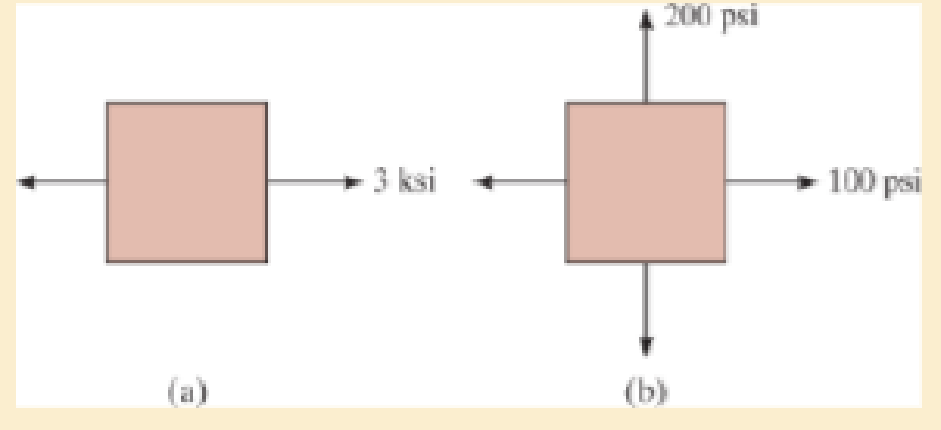
Chapter 9.4, Problem 9.55P
Draw Mohr’s circle trial describes each of the following states of stress
Expert Solution & Answer
Want to see the full answer?
Check out a sample textbook solution
Students have asked these similar questions
The proof stress of a material under tensile loading can be considered as
can be considered as equivalent to the ultimate tensile strength for aluminium alloys
being only applied to engineering steels during a tensile test
the intercept on the stress stain curve for a given strain where a line draw is parallel to the
elastic response line.
the stress at yield for materials have no defined yield stress
Q3b. The stress-strain characteristic curves for materials A, B and C are shown below. Which one statement most accurately describes the
relative toughness and ductility for materials A, B & C?
Material A
Material B
Material C
Strain
Select one:
a. Material A has low toughness, Material B has high ductility and Material C has low toughness.
b. Material A has high toughness, Material B has low ductility and Material C has low toughness.
c. Material A has low ductility, Material B has low toughness and Material C has low toughness.
d. Material A has high ductility, Material B has low toughness and Material C has high toughness.
Stress
Kindly solve this problem with complete solution so that I can Understand.
Correct Final answer: 1400 or 1.4x10^3
Chapter 9 Solutions
EBK MECHANICS OF MATERIALS
Ch. 9.3 - In each case, the state of stress x, y, xy...Ch. 9.3 - Given the state of stress shown on the element,...Ch. 9.3 - Determine the normal stress and shear stress...Ch. 9.3 - Determine the equivalent state of stress on an...Ch. 9.3 - Also, find the corresponding orientation of the...Ch. 9.3 - Determine the equivalent state of stress on an...Ch. 9.3 - Determine the maximum principal stress at point B.Ch. 9.3 - Determine the principal stress at point C.Ch. 9.3 - Prove that the sum of the normal stresses x + y =...Ch. 9.3 - Determine the stress components acting on the...
Ch. 9.3 - Determine the stress components acting on the...Ch. 9.3 - Determine the normal stress and shear stress...Ch. 9.3 - Determine the normal stress and shear stress...Ch. 9.3 - Determine the stress components acting on the...Ch. 9.3 - Determine the stress components acting on the...Ch. 9.3 - Solve Prob.97 using the stress transformation...Ch. 9.3 - Determine the stress components acting on the...Ch. 9.3 - Solve Prob.99 using the stress transformation...Ch. 9.3 - Determine the equivalent state of stress on an...Ch. 9.3 - Determine the equivalent slate of stress on an...Ch. 9.3 - Determine the stress components acting on the...Ch. 9.3 - Determine (a) the principal stresses and (b) the...Ch. 9.3 - The state of stress at a point is shown on the...Ch. 9.3 - Determine the equivalent state of stress on an...Ch. 9.3 - Determine the equivalent state of stress on an...Ch. 9.3 - A point on a thin plate is subjected to the two...Ch. 9.3 - Determine the equivalent state of stress on an...Ch. 9.3 - The stress along two planes at a point is...Ch. 9.3 - The stress acting on two planes at a point is...Ch. 9.3 - The state of stress at a point in a member is...Ch. 9.3 - The grains of wood in the board make an angle of...Ch. 9.3 - The wood beam is subjected to a load of 12 kN. If...Ch. 9.3 - The internal loadings at a section of the beam are...Ch. 9.3 - Solve Prob.925 for point B. 925. The internal...Ch. 9.3 - Solve Prob.925 for point C. 925. The internal...Ch. 9.3 - It is subjected to a torque of 12 kip in. and a...Ch. 9.3 - The bell crank is pinned at A and supported by a...Ch. 9.3 - The beam has a rectangular cross section and is...Ch. 9.3 - A paper tube is formed by rolling a cardboard...Ch. 9.3 - Solve Prob.931 for the normal stress acting...Ch. 9.3 - The 2-in.-diameter drive shaft AB on the...Ch. 9.3 - Determine the principal stresses in the...Ch. 9.3 - The internal loadings at a cross section through...Ch. 9.3 - The internal loadings at a cross section through...Ch. 9.3 - The shaft has a diameter d and is subjected to the...Ch. 9.3 - The steel pipe has an inner diameter of 2.75 in....Ch. 9.3 - Solve Prob.938 for point B, w1ich is located on...Ch. 9.3 - The wide-flange beam is subjected to the 50-kN...Ch. 9.3 - Solve Pro b. 9-40 for point B located on the web...Ch. 9.3 - The box beam is subjected to the 26-kN force that...Ch. 9.3 - Solve Prob.942 for point B. 942. The box beam is...Ch. 9.4 - Use Mohrs circle to determine the normal stress...Ch. 9.4 - Also, find the corresponding orientation of the...Ch. 9.4 - Draw Mohrs circle and determine the principal...Ch. 9.4 - Determine the principal stresses at a point on the...Ch. 9.4 - Determine the principal stresses at point A on the...Ch. 9.4 - Point A is just below the flange.Ch. 9.4 - Solve Prob.9-2 using Mohrs circle. 92. Determine...Ch. 9.4 - Solve Prob.93 using Mohrs circle. 93. Determine...Ch. 9.4 - Solve Prob.96 using Mohrs circle. 96. Determine...Ch. 9.4 - Solve Prob.911 using Mohrs circle. 911. Determine...Ch. 9.4 - Solve Prob.915 using Mohrs circle. 915. The state...Ch. 9.4 - Solve Prob.916 using Mohrs circle. 916. Determine...Ch. 9.4 - Mohrs circle for the state of stress is shown in...Ch. 9.4 - Determine (a) the principal stresses and (b) the...Ch. 9.4 - Determine (a) the principal stresses and (b) the...Ch. 9.4 - Determine the equivalent state of stress if an...Ch. 9.4 - Draw Mohrs circle that describes each of the...Ch. 9.4 - Draw Mohrs circle trial describes each of the...Ch. 9.4 - Determine (a) the principal stresses and (b) the...Ch. 9.4 - Determine (a) the principal stresses and (b) the...Ch. 9.4 - Determine (a) the principal stresses and (b) the...Ch. 9.4 - Determine (a) the principal stresses and (b) the...Ch. 9.4 - Determine (a) the principal stresses and (b) the...Ch. 9.4 - Draw Mohrs circle that describes each of the...Ch. 9.4 - The grains of wood in the board make an angle of...Ch. 9.4 - The post is fixed supported at its base and a...Ch. 9.4 - Determine the principal stresses, the maximum...Ch. 9.4 - The thin-walled pipe has an inner diameter of 0.5...Ch. 9.4 - The frame supports the triangular distributed load...Ch. 9.4 - The frame supports the triangular distributed load...Ch. 9.4 - The rotor shaft of the helicopter is subjected to...Ch. 9.4 - The pedal crank for a bicycle has the cross...Ch. 9.4 - A spherical pressure vessel has an inner radius of...Ch. 9.4 - The cylindrical pressure vessel has an inner...Ch. 9.4 - Determine the normal and shear stresses at point D...Ch. 9.4 - Determine the principal stress at point D, Which...Ch. 9.4 - If the box wrench is subjected to the 50 lb force,...Ch. 9.4 - If the box wrench is subjected to the 50-lb force,...Ch. 9.4 - The post is fixed supported at its base and the...Ch. 9.5 - Draw the three Mohrs circles that describe each of...Ch. 9.5 - Draw the three Mohrs circles that describe the...Ch. 9.5 - Draw the three Mohrs circles that describe the...Ch. 9.5 - Determine the principal stresses and the absolute...Ch. 9.5 - Determine the principal stresses and the absolute...Ch. 9.5 - Determine the principal stresses and the absolute...Ch. 9.5 - Determine the principal stresses and the absolute...Ch. 9.5 - The solid shaft is subjected to a torque, bending...Ch. 9.5 - The frame is subjected to a horizontal force and...Ch. 9.5 - The bolt is fixed to its support at C. If a force...Ch. 9.5 - The bolt is fixed to its support at C. If a force...Ch. 9 - Prob. 9.1RPCh. 9 - The steel pipe has an inner diameter of 2.75 in....Ch. 9 - Determine the equivalent state of stress If an...Ch. 9 - The crane is used to support the 350-lb load....Ch. 9 - Determine the equivalent state of stress on an...Ch. 9 - The propeller shaft of the tugboat is subjected to...Ch. 9 - Determine the principal stresses in the box beam...Ch. 9 - Determine (a) the principal stresses and (b) the...Ch. 9 - Determine the stress components acting on the...
Knowledge Booster


Learn more about
Need a deep-dive on the concept behind this application? Look no further. Learn more about this topic, mechanical-engineering and related others by exploring similar questions and additional content below.Similar questions
- How many independent stress components are needed to define the stress state of a point in 3-D?arrow_forward(a) Construct Mohr's circle for an element in a uniaxial state of stress (b) Use this Mohr's circle to derive the equation for the normal stress On and shear stress En on the n-face. The equations should depend on Ox and θ (c) Use the Mohr's circle to determine the planes on which the maximum shear stress acts. Sketch a properly oriented maximum-shear-stress element and indicate the normal and shear stresses acting on its faces. Ơn nt o, Note: for (b), the angle θ is between 0 and 90° and is positivearrow_forwardStress Strain Diagram The Data shown in the table have been obtained from a tensile test conducted on a high-strength steel. The test specimen had a diameter of 0.505 inch and a gage length of 2.00 inch. Using software. plot the Stress-Strain Diagram for this steel and determine its: A= TTdT(050s A %3D 1. Proportional Limit, 2. Modulus of Elasticity, 3. Yield Strength (SY) at 0.2% Offset, 4. Ultimate Strength (Su), 5. Percent Elongation in 2.00 inch, 6. Percent Reduction in Area, 7. Present the results (for Steps 1-6) in a highly organized table. e Altac ie sheet (as problelle 4 A = 0.2.002 BEOINNING of the effort Elongation (in) Elongation (In) Load Load #: #3 (Ib) (Ib) 1 0.0170 15 12,300 0.0004 1,500 16 12,200 0.0200 0.0010 3. 3,100 17 12,000 0.0275 0.0016 4,700 18 13,000 0.0335 5. 6,300 0.0022 19 15,000 0.0400 0.0026 6. 8,000 20 16,200 0.055 0.0032 9,500 21 17,500 0.0680 0.0035 8. 11,000 22 18,800 0.1080 0.0041 11,800 23 19,600 0.1515 0.0051 24 20,100 0.2010 10 12,300 0.0071 25…arrow_forward
- The main stresses and directions and the maximum shear stress;The tension state for a 30° clockwise rotation.Mohr's Circle.arrow_forwardChoose correct answer: Maximum stress on a principle plane is Tangential stress shear stress Normal Stress Resultant stressarrow_forwardAnswer the questions below for the following system. Young's modulus and Poison's ratio can be taken as 200 GPa and 0.3, respectively. a) Calculate and determine the stress state for point H using undergraduate level solid mechanics knowledge? b) Determine the principal stress values at point H using undergraduate level solid mechanics knowledge? Top view of section where H is located Point H no 300 mm 120 mm C .H 540 mm A Diameter of the pipe d=36 mm P=900 Narrow_forward
- he region of safety in maximum shear stress theory contains which of the given shape *arrow_forwardUsing the tensile test simulation tool, a. generate the stress-strain curve for aluminum b. Indicate the following points in the stress-strain curve for aluminum and give the corresponding values: limit of proportionality elastic limit 0.2% offset yield stress (include the graph illustrating how this was determined) ultimate stress fracture stress c. Calculate modulus of elasticity. d. compare aluminum with nylon (include the related graph) and answer the following: Which has higher tensile strength? Provide the necessary values to support the answer. Which is stiffer? Support your answer with calculations.arrow_forwardExample: Convert the change in length data in Table 3-2 to engineering stress and strain and plot a stress-strain curve Homework- help Table 3-2 The results of a tensile test of a 0.505 in. diameter aluminum alloy test bar, initial length (1o) = 2 in. Calculated LTO Load (Ib) Change in Length (in.) Stress (psi) Strain (in./in.) 0.000 1000 0.001 0.0005 4,993 14,978 24,963 34,948 37,445 39,442 39,941 39,691 37,944 3000 0.003 0.0015 5000 0.005 0.0025 7000 0.007 0.0035 7500 0.030 0.0150 7900 0.080 0.0400 8000 (maximum load) 0.120 0.0600 7950 0.160 0.0800 7600 (fracture) 0.205 0.1025arrow_forward
- Answer the questions below for the following system. Young's modulus and Poison's ratio can be taken as 200 GPa and 0.3, respectively. a) Calculate and determine the stress state for point H using undergraduate level solid mechanics knowledge? b) Determine the principal stress values at point H using undergraduate level solid mechanics knowledge Top view of section where H is located O Point H 300 mm 120 mm 540 mm .H Diameter of the pipe d=36 mm P=900 Narrow_forwardPlease match different stresses to the stress value corresponding to the different points on the Stree-strain diagram of a low carbon steel. Proportional Limit Ultimate Strength Tensile Yield Strength A. A B. B C. Darrow_forwardA steel pipe with an outside diameter of 115 mm and an inside diameter of 105 mm supports the loadings shown. Assume a = 510 mm, b = 230 mm, P = 20 kN, P, = 16 kN, and P; = 11 kN. (a) Determine the normal and shear stresses on the top surface of the pipe at point H. (b)Determine the principal stresses and maximum in-plane shear stress magnitude at point H and show the orientation of these stresses on an appropriate sketch. a P: P H Karrow_forward
arrow_back_ios
SEE MORE QUESTIONS
arrow_forward_ios
Recommended textbooks for you
 Elements Of ElectromagneticsMechanical EngineeringISBN:9780190698614Author:Sadiku, Matthew N. O.Publisher:Oxford University Press
 Mechanics of Materials (10th Edition)Mechanical EngineeringISBN:9780134319650Author:Russell C. HibbelerPublisher:PEARSON
 Thermodynamics: An Engineering ApproachMechanical EngineeringISBN:9781259822674Author:Yunus A. Cengel Dr., Michael A. BolesPublisher:McGraw-Hill Education
 Control Systems EngineeringMechanical EngineeringISBN:9781118170519Author:Norman S. NisePublisher:WILEY
 Mechanics of Materials (MindTap Course List)Mechanical EngineeringISBN:9781337093347Author:Barry J. Goodno, James M. GerePublisher:Cengage Learning
 Engineering Mechanics: StaticsMechanical EngineeringISBN:9781118807330Author:James L. Meriam, L. G. Kraige, J. N. BoltonPublisher:WILEY
Elements Of Electromagnetics
Mechanical Engineering
ISBN:9780190698614
Author:Sadiku, Matthew N. O.
Publisher:Oxford University Press
Mechanics of Materials (10th Edition)
Mechanical Engineering
ISBN:9780134319650
Author:Russell C. Hibbeler
Publisher:PEARSON
Thermodynamics: An Engineering Approach
Mechanical Engineering
ISBN:9781259822674
Author:Yunus A. Cengel Dr., Michael A. Boles
Publisher:McGraw-Hill Education
Control Systems Engineering
Mechanical Engineering
ISBN:9781118170519
Author:Norman S. Nise
Publisher:WILEY
Mechanics of Materials (MindTap Course List)
Mechanical Engineering
ISBN:9781337093347
Author:Barry J. Goodno, James M. Gere
Publisher:Cengage Learning
Engineering Mechanics: Statics
Mechanical Engineering
ISBN:9781118807330
Author:James L. Meriam, L. G. Kraige, J. N. Bolton
Publisher:WILEY
An Introduction to Stress and Strain; Author: The Efficient Engineer;https://www.youtube.com/watch?v=aQf6Q8t1FQE;License: Standard YouTube License, CC-BY