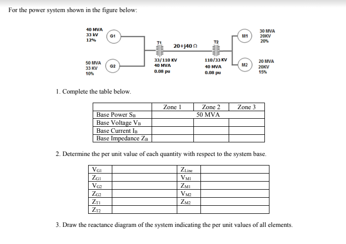
For the power system shown in the figure below: 40 MVA 30 MVA 20KV 33 kv 12% M1 20% 20+j40 A 33/110 KV 40 MVA 110/33 KV 50 MVA 33 KV 20 MVA 20KV 15% G2 40 MVA M2 10% 0.08 pu 0.08 pu 1. Complete the table below. Zone 1 Zone 2 Zone 3 Base Power SB Base Voltage VB Base Current In Base Impedance ZB 50 MVA 2. Determine the per unit value of each quantity with respect to the system base. Vai ZGI Va ZLine VMI ZMI VM2 ZTI ZM2 Z12 3. Draw the reactance diagram of the system indicating the per unit values of all elements.
For the power system shown in the figure below: 40 MVA 30 MVA 20KV 33 kv 12% M1 20% 20+j40 A 33/110 KV 40 MVA 110/33 KV 50 MVA 33 KV 20 MVA 20KV 15% G2 40 MVA M2 10% 0.08 pu 0.08 pu 1. Complete the table below. Zone 1 Zone 2 Zone 3 Base Power SB Base Voltage VB Base Current In Base Impedance ZB 50 MVA 2. Determine the per unit value of each quantity with respect to the system base. Vai ZGI Va ZLine VMI ZMI VM2 ZTI ZM2 Z12 3. Draw the reactance diagram of the system indicating the per unit values of all elements.

Introductory Circuit Analysis (13th Edition)
13th Edition
ISBN:9780133923605
Author:Robert L. Boylestad
Publisher:Robert L. Boylestad
Chapter1: Introduction
Section: Chapter Questions
Problem 1P: Visit your local library (at school or home) and describe the extent to which it provides literature...

Related questions
Question
Transcribed Image Text:For the power system shown in the figure below:
40 MVA
30 MVA
20KV
20%
33 kv
G1
M1
12%
20+j40 n
33/110 KV
110/33 KV
20 MVA
50 MVA
M2
G2
40 MVA
40 MVA
20KV
15%
33 KV
10%
0.08 pu
0.08 pu
1. Complete the table below.
Zone 1
Zone 2
Zone 3
Base Power SB
50 MVA
Base Voltage VB
Base Current IB
Base Impedance ZB
2. Determine the per unit value of each quantity with respect to the system base.
VGI
ZLine
ZGI
VMI
ZMI
ZG2
VM2
ZTI
ZM2
Z12
3. Draw the reactance diagram of the system indicating the per unit values of all elements.
Expert Solution
This question has been solved!
Explore an expertly crafted, step-by-step solution for a thorough understanding of key concepts.

This is a popular solution!

Trending now
This is a popular solution!

Step by step
Solved in 7 steps with 7 images

Knowledge Booster


Learn more about
Need a deep-dive on the concept behind this application? Look no further. Learn more about this topic, electrical-engineering and related others by exploring similar questions and additional content below.Recommended textbooks for you
Introductory Circuit Analysis (13th Edition)
Electrical Engineering
ISBN:
9780133923605
Author:
Robert L. Boylestad
Publisher:
PEARSON

Delmar's Standard Textbook Of Electricity
Electrical Engineering
ISBN:
9781337900348
Author:
Stephen L. Herman
Publisher:
Cengage Learning

Programmable Logic Controllers
Electrical Engineering
ISBN:
9780073373843
Author:
Frank D. Petruzella
Publisher:
McGraw-Hill Education
Introductory Circuit Analysis (13th Edition)
Electrical Engineering
ISBN:
9780133923605
Author:
Robert L. Boylestad
Publisher:
PEARSON
Delmar's Standard Textbook Of Electricity
Electrical Engineering
ISBN:
9781337900348
Author:
Stephen L. Herman
Publisher:
Cengage Learning
Programmable Logic Controllers
Electrical Engineering
ISBN:
9780073373843
Author:
Frank D. Petruzella
Publisher:
McGraw-Hill Education

Fundamentals of Electric Circuits
Electrical Engineering
ISBN:
9780078028229
Author:
Charles K Alexander, Matthew Sadiku
Publisher:
McGraw-Hill Education

Electric Circuits. (11th Edition)
Electrical Engineering
ISBN:
9780134746968
Author:
James W. Nilsson, Susan Riedel
Publisher:
PEARSON

Engineering Electromagnetics
Electrical Engineering
ISBN:
9780078028151
Author:
Hayt, William H. (william Hart), Jr, BUCK, John A.
Publisher:
Mcgraw-hill Education,